Catalyst.earth Logo
Catalyst.earth Logo

Orthorectification, Image Alignment, and Fusion

Image of a satellite scanning the ground in a forest area

This tutorial covers the orthorectification, image alignment, and spectral fusion workflow in CATALYST Professional. It uses tools available in CATALYST OrthoEngine and Focus.

Misalignment between multispectral and panchromatic imagery is a common issue in remote sensing workflows. Since panchromatic images are captured at a finer resolution and sometimes different viewing angles than their multispectral counterparts, small positional shifts and offsets can occur between the two images. If not corrected, these misalignments can lead to artifacts, such as colour fringing, in the pansharpened product.

In this workflow, orthorectification is performed first to correct geometric distortions and place each image into a consistent map coordinate system. Once both datasets are spatially corrected, image alignment is applied before image fusion to refine any offsets and ensure the multispectral and panchromatic imagery line up appropriately.

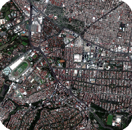
This tutorial walks through this workflow using optical satellite imagery from Beijing-3.

1. Orthorectification

You can find more information on the orthorectification process from the CATALYST Professional Help Documentation and Tutorials webpage.

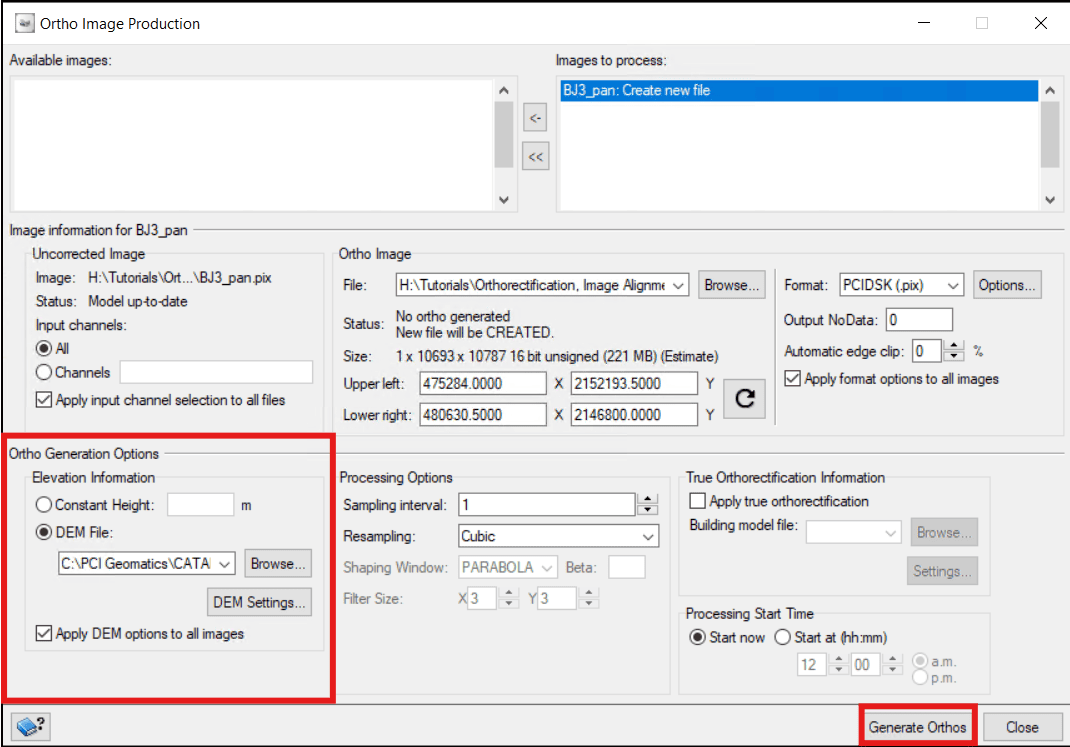
This workflow consists of two orthorectification steps. First, the panchromatic image is orthorectified to produce a reference image. This reference is then used to guide the orthorectification of the multispectral image to the panchromatic image.

1.1. Orthorectifying the Panchromatic Image

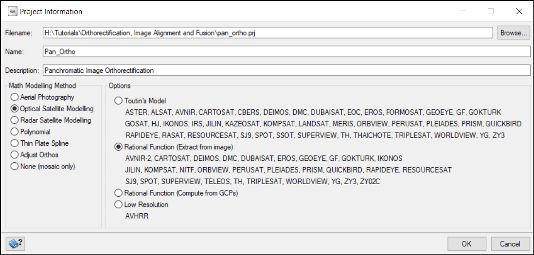
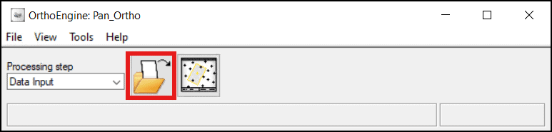
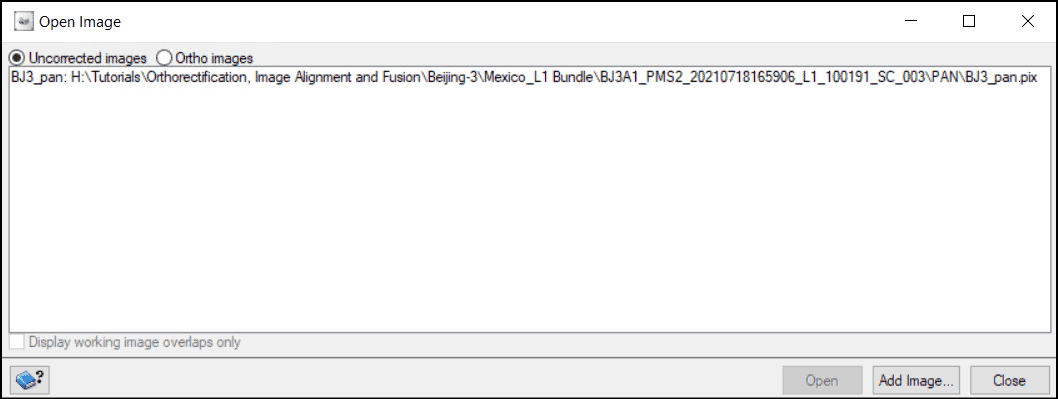
To begin, create the OrthoEngine project for the panchromatic image.

  1. From the CATALYST Professional toolbar, open OrthoEngine.
  2. Create a new project (File > New):
    • Browse to the project folder and enter the project file name.
    • Enter a project Name and Description (optional).
    • Set the Math Modelling Method to Optical Satellite Modelling.
    • Select the Rational Function (Extract from image) option.
  3. Click OK.


  4. Change the Processing Step to Data Input.
  5. Click the Open a new or existing image icon.


  6. Click Add Image... and navigate to the panchromatic image.
    • A window appears asking if you want to import the data to a PIX file to optimize processing. Click Yes and give the pix file a name.
    • Another window appears asking to create overviews. Click Yes.
  7. Once the overviews have been created, close the Open Image window.


  8. Change the Processing Step to Ortho Generation and select Schedule ortho generation. The Ortho Image Production window opens.
  9. Move the panchromatic image from the Available images section to the Images to process section.
  10. In the Ortho Generation Options section, select DEM File and navigate to your DEM of choice.


  11. Click Generate Orthos.
1.2. Orthorectifying the Multispectral Image

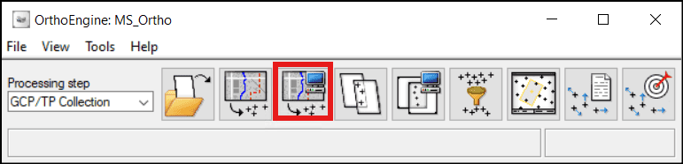
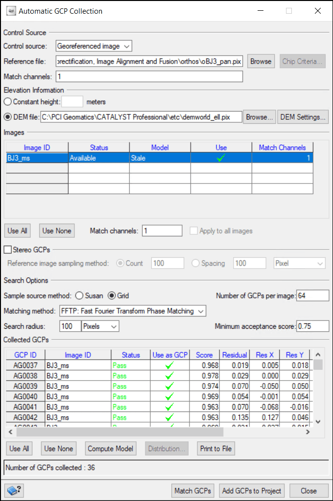
Now that the panchromatic image has been orthorectified, it can serve as a reference for orthorectifying the multispectral image.

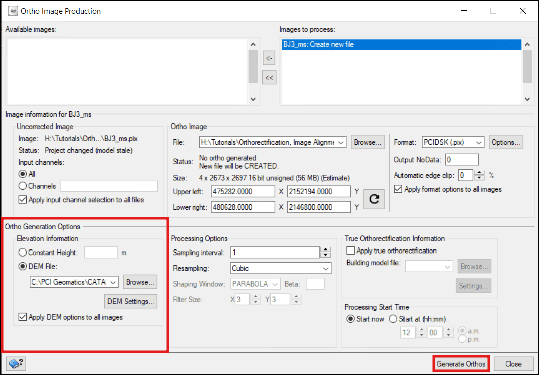
To orthorectify the multispectral image:

  1. Create a new OrthoEngine project for the multispectral image using the same settings as with the panchromatic OrthoEngine project.
  2. Change the Processing Step to Data Input.
  3. Click the Open a new or existing image icon.
  4. Click Add Image... and this time, navigate to the multispectral image.
    • A window appears asking if you want to import the data to a PIX file to optimize processing. Click Yes and give the pix file a name.
    • Another window appears asking to create overviews. Click Yes.
  5. Once the overviews have been created, close the Open Image window.
  6. Change the Processing Step to GCP/TP Collection. Here, you can choose to collect GCPs manually or automatically. This tutorial uses the automatic option.
  7. Select Collect GCPs Automatically. The Automatic GCP Collection window opens.


  8. Set the following parameters:
    • Control Source: Georeferenced image.
    • Reference file: the orthorectified panchromatic image.
    • Elevation Information: DEM - enter the path to the DEM.
  9. Click Match GCPs.
  10. Once the GCPs have been collected, select Compute Model.
    • Some points can be removed if the residuals are high.
  11. Click Add GCPs to Project and close the window.


    Now that the model has been improved with GCPs, the multispectral ortho image can be created.
  12. Change the Processing Step to Ortho Generation and select Schedule ortho generation. The Ortho Image Production window opens.
  13. Move the multispectral image from the Available images section to the Images to process section.
  14. In the Ortho Generation Options section, select DEM File and navigate to the DEM


  15. Click Generate Orthos.

2. Image Alignment & Fusion

There are two main image fusion options in CATALYST Professional - Pansharpening & Multi-Resolution Analysis Fusion (MRAFUSION). Learn more about the differences between the PANSHARP and MRAFUSION algorithms here - Image Fusion: Comparing PANSHARP And MRAFUSION.

Pansharpening can be performed with misalignment correction before the fusion. This is where the APANSHARP algorithm comes in. This can be beneficial for aligning images from different sensors.

2.1. OPTION 1: Pansharpening with Alignment

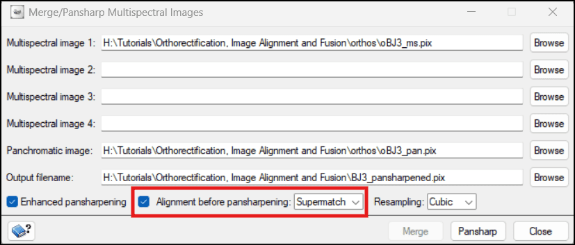
The APANSHARP algorithm can be used to align the multispectral and panchromatic images before fusion. This algorithm can be run in OrthoEngine.

To pansharpen with alignment in OrthoEngine:

  1. From the CATALYST Professional toolbar, open OrthoEngine.
  2. Create a new project (File > New):
    • Browse to the project folder and enter the project file name.
    • Enter a project Name and Description (optional).
    • Set the Math Modelling Method to Optical Satellite Modelling.
    • Select the Rational Function (Extract from image) option.
  3. Click OK.
  4. Navigate to Tools > Merge/Pansharp Multispectral Images...
  5. In the Multispectral image 1 field, browse to the orthorectified multispectral image.
  6. In the Panchromatic image field, browse to the orthorectified panchromatic image.
  7. Specify an output name in the Output filename field.
  8. Ensure Alignment before pansharpening is selected. This triggers the APANSHARP algorithm instead of PANSHARP.
  9. Select the Pansharp button and close the window once the process is done.

2.2. OPTION 2: Super Registration and MRAFUSION

Another option to correct misalignment before image fusion is to use the Super Registration workflow to co-register the images before running the MRAFUSION algorithm. Learn more about the Super Registration workflow here - Super Registration In CATALYST Professional. The code below runs SUPERMATCH, SUPERAPPLY and MRAFUSION in a single script.

from pci import algo

# Input Variables
# Ortho file to be shifted
image = r"H:\Tutorials\Orthorectification, Image Alignment and Fusion\orthos\oBJ3_ms.pix"

# Reference ortho file
ref =r"H:\Tutorials\Orthorectification, Image Alignment and Fusion\orthos\oBJ3_pan.pix"

# Offset file
offset = r"H:\Tutorials\Orthorectification, Image Alignment and Fusion\align_fusion\BJ3_offsets.pix"

# Output registered image
reg_image = r"H:\Tutorials\Orthorectification, Image Alignment and Fusion\align_fusion\BJ3_superreg.pix"

# Output fused image
fuse_image = r"H:\Tutorials\Orthorectification, Image Alignment and Fusion\align_fusion\BJ3_mrafusion.pix"

# Run SUPERMATCH
algo.supermatch(fili=image, dbic=[1], filref=ref, dbic_ref=[1], searchr=[30],
                searchun="METER", fftsize=[64], minscore=[0.8], pntgrid=[25],
                pntstrat="FIRST", pntclean="MED", filo=offset, pointapp="OFF")

# Run SUPERAPPLY
algo.superapply(fili=image, filoff=offset, dbdc=[1, 2], filo=reg_image)

# Run MRAFUSION
algo.mrafusion (fili=reg_image, fili_pan=ref, srcbgd='FILE', radapt='YES', edgeshar=[1],
           filo=fuse_image, ftype='PIX')
envelopephone-handsetcross