The DEM Editing tool is a fast and intuitive solution designed to smooth out elevation irregularities and improve the accuracy of your digital elevation model (DEM). A more refined DEM leads to higher-quality orthorectified imagery.
The Focus DEM Editing window requires only a DEM input—a raster channel in a writable format. However, to take full advantage of the tool’s capabilities and produce optimal results, it’s recommended that the DEM contain supplementary information. If the DEM was generated from epipolar images, using that source imagery during editing can enhance accuracy.
The DEM Editor works in a mono viewing environment, so no special 3D equipment is required. It automatically regenerates stereo ortho images within user-defined regions to assess vertical accuracy. This enables quick inspection of specific areas of the DEM, especially in complex terrain, helping users preview the quality of the resulting ortho images.
By identifying and correcting elevation errors early in the process, Ortho-Mosaic generation becomes more efficient and cost-effective, avoiding the need to reprocess flawed output caused by DEM issues.
To follow along with the tutorial, download the required tutorial data provided below.
The tutorial is divided into two sections:
Advanced Editing – A detailed guide on using multiple polygons to refine and correct a DEM.
Quick Demo – A brief walkthrough to help you get familiar with the DEM Editing interface and workflow.
Resources
Tutorial Data - Live DEM Editing Tutorial Data
DEM Editing Help Documentation - Using the DEM Editing Toolbar
Section 1: Editing An Urban Area
- Open Focus and load the waterfalls_demaerial_intro.gpr file. You can do this by dragging and dropping the file into the Maps tab or by clicking File > Open. The default view is grayscale.
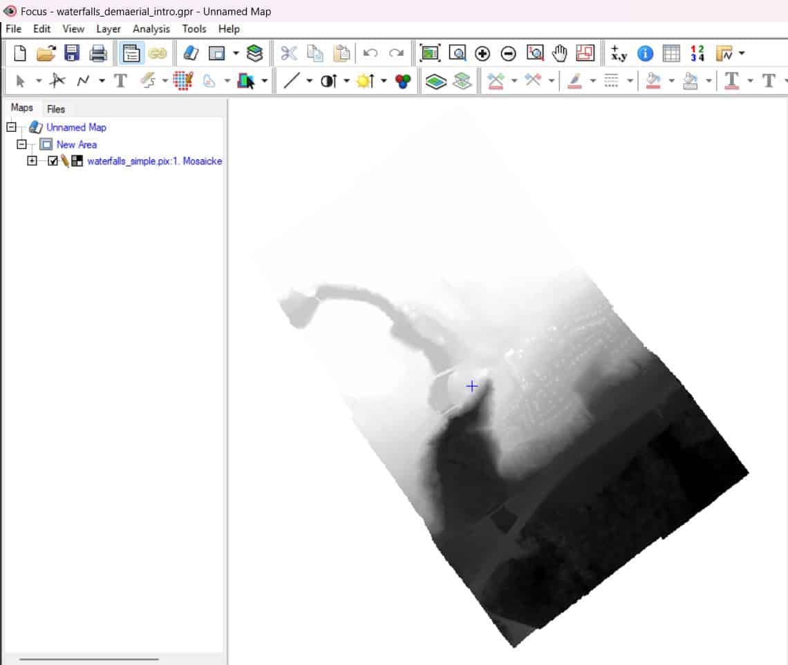
- In the Focus menu bar, click on the Layer dropdown menu and select DEM Editing… The Live DEM Editing window opens, and the DEM is now rendered as a dynamic pseudo-colour hillshade.

NOTE – The Display DEM button lets you switch between a colored shaded relief DEM view and the ortho preview. An ortho preview is a preliminary ortho mosaic that’s been created using the digital terrain model calculated when you created the DSM.
- Using the Zoom In tool in Focus, zoom into an area you wish to edit. You will notice that the preliminary ortho mosaic shows some issues. The rooflines are not straight, and there is some blurring around trees. Using the DEM editor, we can flatten the elevation and create a better-looking ortho.
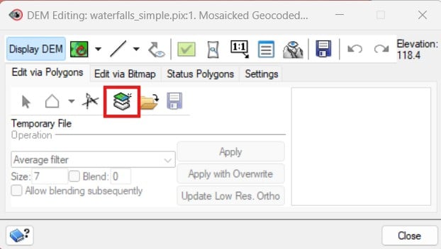
- Click on the Create a polygon layer button, and use the New Shapes tool in Focus to digitize a polygon around the dwellings you want to edit.
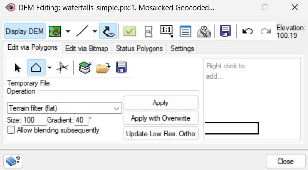
- In the DEM Editing window, choose Terrain filter (flat), with Size = 100 (search radius) and Gradient = 40%
- Click Apply. Notice that the dwellings have been removed, as the elevation has been averaged out with the ground.
- Still in the DEM Editing window, click on the Define Preview Region button
 .
.
- Draw a polygon around the area that has been edited. The Full Res: Ortho Preview window will open. NOTE: Loading the area at 1:1 gives you a view of the end ortho mosaic that will be generated once you decide to create an ortho of the area.
- In the Full Res: Ortho Preview window, you can click on the Left and Right drop-down arrows. This will let you choose between different views for the output ortho. When you compare the filtered ortho preview to the unfiltered ortho preview in the Focus window, you will notice the building outlines are now straight and the trees are no longer smeared. This is a result of removing the distortion and averaging out the elevation values.
- The edited DEM can now be saved using the Save icon in the DEM Editing window.
At this point, the DEM has been accurately edited so that it can be used for a variety of applications such as orthorectification and mosaicking.
Section 2: Fixing A Bridge In A DEM
The following section of the tutorial shows how to edit bridges and ramps using the DEM Editing tool.
- Load the overpass_bridgefix.gpr DEM into Focus by dragging and dropping the file into the Maps tab or by clicking File > Open.
- In the Focus menu bar, click on the Layer dropdown menu and select DEM Editing…
- The Live DEM Editing window opens, and the DEM is now rendered as a dynamic pseudo-colour hillshade. NOTE: Clicking on Display DEM will change the DEM view from a colored DSM view to an ortho preview. Ortho preview is a preliminary ortho mosaic created using the digital terrain model of the surface terrain model.
Section 2.1 - Editing The Elevated Bridges And Ramps
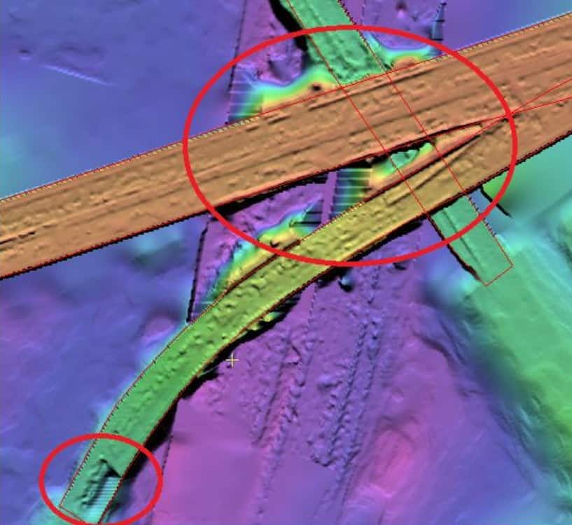
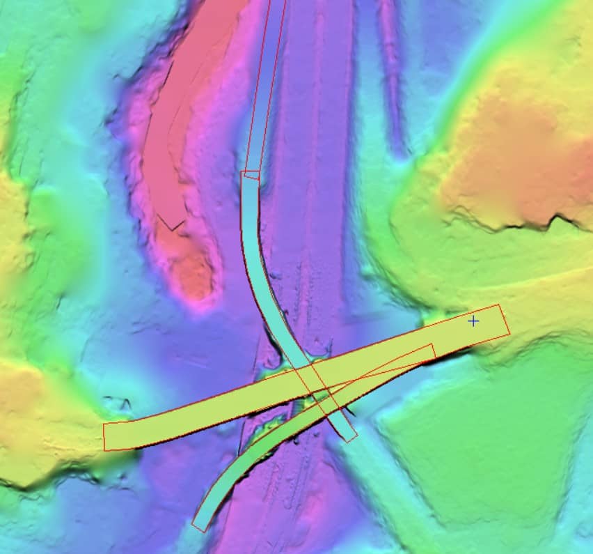
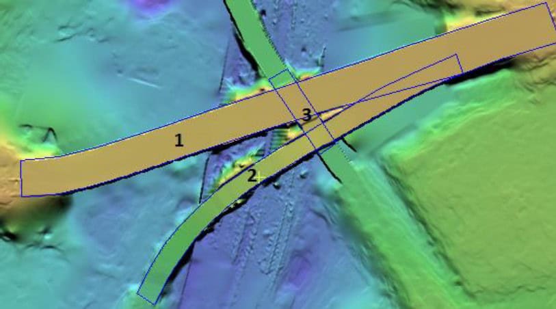
The area of interest for this tutorial will be the bridge and ramp shown in the image below.
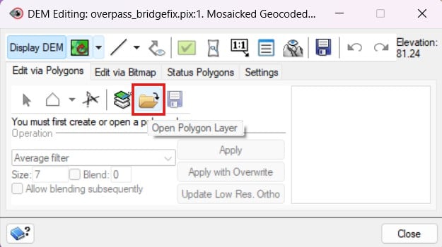
- In the DEM Editing window, ensure that the Edit via Polygons tab is the active tab and click on the Open Polygon Layer button.
- In the File dropdown, select the bridgefix_vec.pix > DEM Editing Polygons layer.

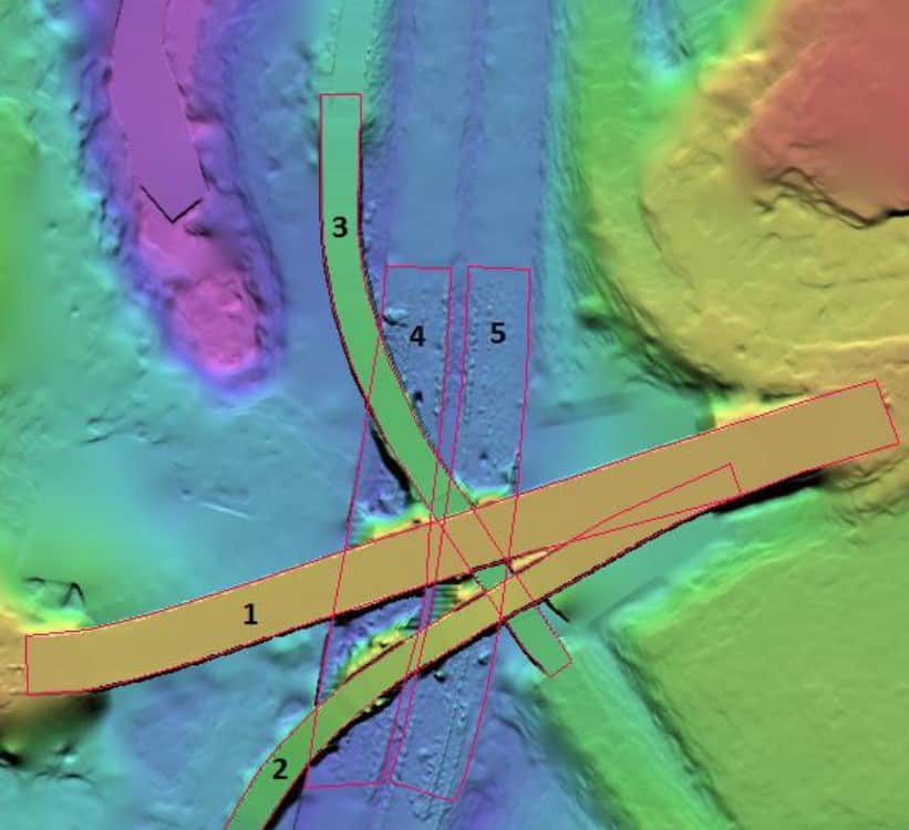
- Click OK. A vector layer is added to the map containing a set of polygons that follow the bridges to be edited. Use the following figure to identify each polygon by a number:

- On the Focus toolbar, click on the Selection Tools button
 .
.
- Select polygon 1.
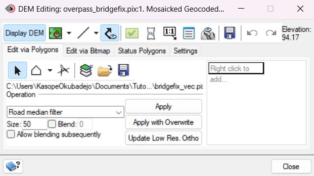
- In the DEM Editing window, change the Operation to Road Median Filter and the Size to 50.
- Click Apply with Overwrite.
NOTE: The Apply with Overwrite allows the DEM operation to be applied to all pixels under the selected polygon. This includes pixels covered by another polygon. The Apply with Overwrite option is used here because polygon 3 has a segment that intersects polygon 1. Since polygon 1 is the bridge on top, we need to use the Apply with Overwrite.
- Select polygon 2
- Using the same settings as polygon 1, click Apply with Overwrite
- Select polygon 3
- Using the same settings as polygon 1, click Apply. Since polygon 3 is the lower bridge segment, use Apply (not Apply with overwrite) so the elevation information of the bridges above is not overwritten.
NOTE: Ctrl+Z can always be used to undo an accidental edit
- Select polygon 4
- Using the same settings as polygon 1, click Apply with Overwrite
The bridges and ramps in this area should now be accurate and smooth. We now need to clean up underneath the bridge.
Section 2.2 - Editing The Road Under The Bridges And Ramps
- In the DEM Editing window, ensure that the Edit via Polygons tab is the active tab and click on the Open Polygon Layer button.
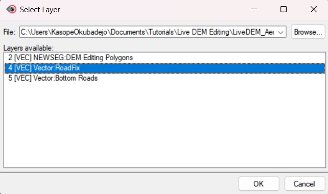
- In the File dropdown, select the second polygon layer in the list - bridgefix_vec.pix > RoadFix layer.
- A new set of polygons will be added to the map. The figure below provides numbers for each of the polygons. Polygons 1 and 2 are not used for any editing in this step. They are used to prevent the operation performed on polygon 3 from overwriting the information on polygons 1 and 2.
- Using the Selection tool , select polygon 3.
- In the DEM Editing window, change the Operation to Opposite ends fill (blend all sides).
- Click Apply. The road underneath polygons 1 and 2 is now cleaned up.
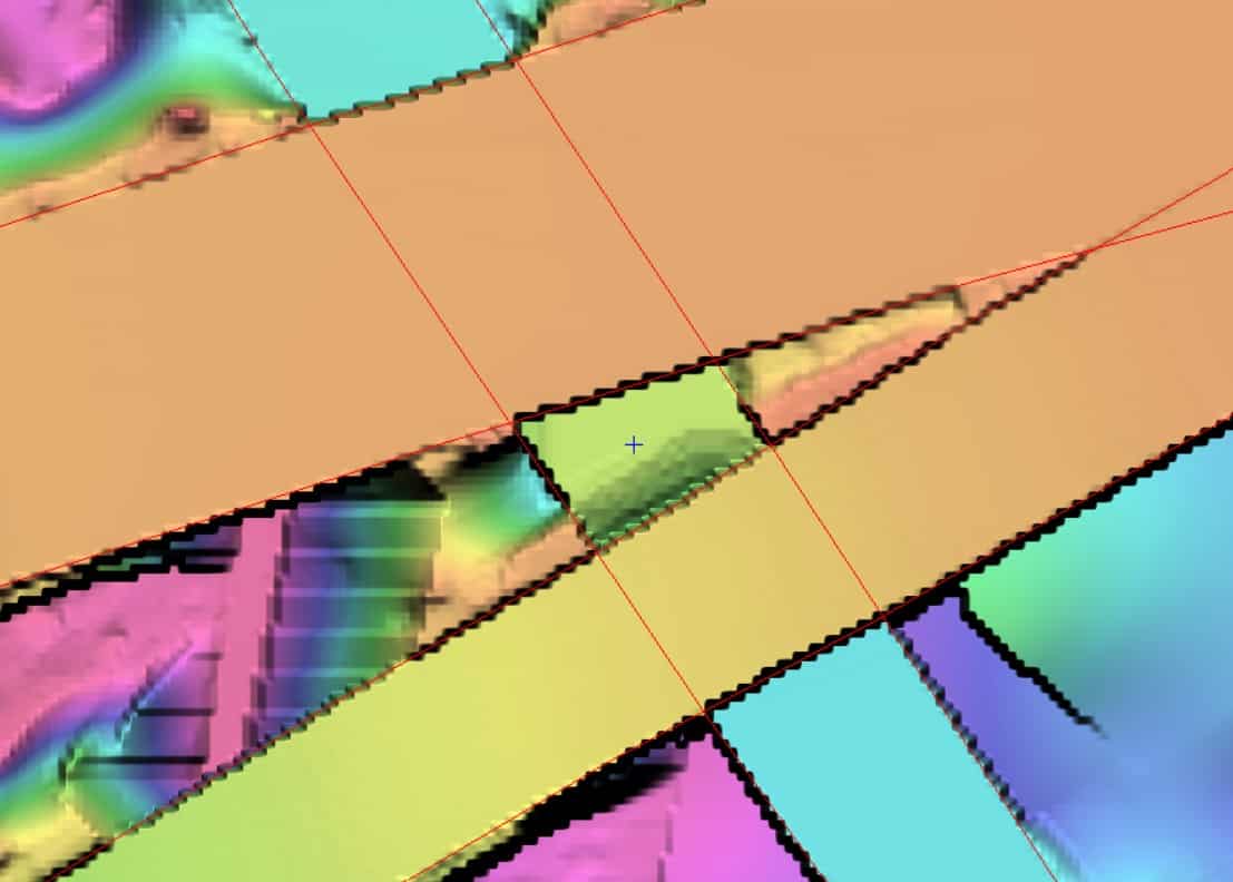
Before:
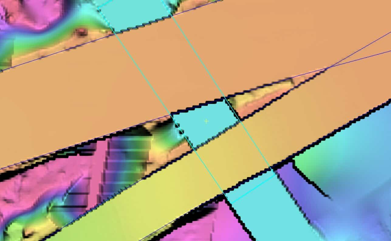
After:
- Ensure the Edit via Polygons tab is still active in the DEM Editing window. Click the Open Polygon Layer button
- In the Select Layer window, click on the File dropdown list and select bridgefix_vec.pix > BottomRoads
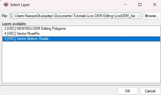
- Click OK
- Polygons 1, 2 and 3 are not used for any editing in this step. Rather, they are used to prevent the operation performed on polygons 4 and 5 from overwriting the information on polygons 1, 2 and 3.
- Using the Selection tool , select polygon 4
- In the DEM Editing window, change the Operation to Opposite ends fill (blend all sides)
- Click Apply. The mess along the road under polygon 4 is cleaned, and the road is now smooth.
- Select polygon 5
- Using the same operation as above, click Apply. The mess along the road under polygon 5 is cleaned, and the road is now smooth.
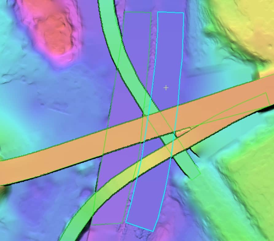
This DEM now accurately represents the elevations and slopes of the interchange. The result of the edits should look similar to the following diagram:
Section 2.3 - Viewing A Defined Region
- Make sure that you are displaying the DEM with surface (man-made) features removed from the plateau.
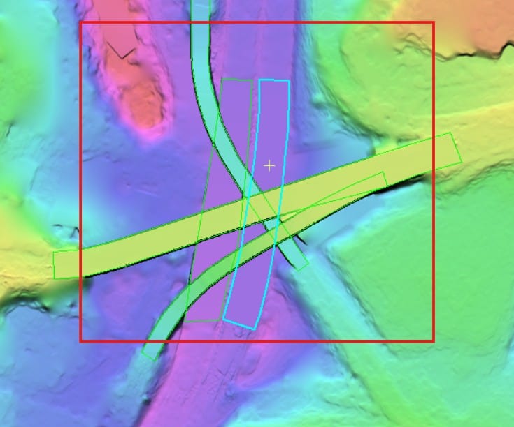
- In the DEM Editing window, click on the Define Preview Region button .
- With the tool selected, draw a bounding box in roughly the same area as displayed in the figure directly below (red box):
- In the 1:1 Ortho Preview window, click the Flicker Left/Right Image button
 .
.
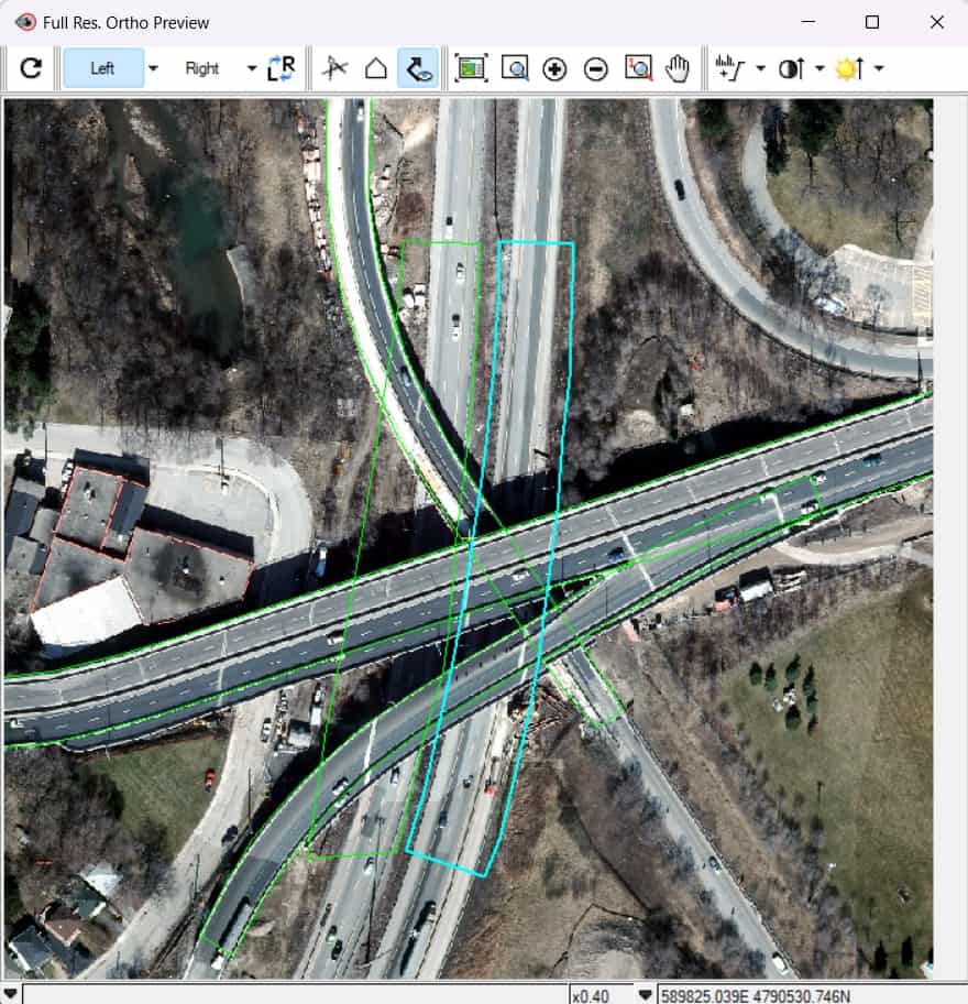
The left and right stereo images will begin flickering back and forth in the Full Res: Ortho Preview window. The edited DEM can now be saved using the Save icon in the DEM Editing window. At this point the DEM has been accurately edited so that it can be used for a variety of applications such as orthorectification and mosaicking.
For any questions or feedback, please contact our support team at [email protected].