Adjust Orthos - TPS Model is a tool designed to fix misalignments between orthos using a thin plate spline method. This method allows for an overall better mosaic. It is common to have misalignment between orthos due to inaccuracy in ground control points (GCPs) or a low-accuracy DEM.
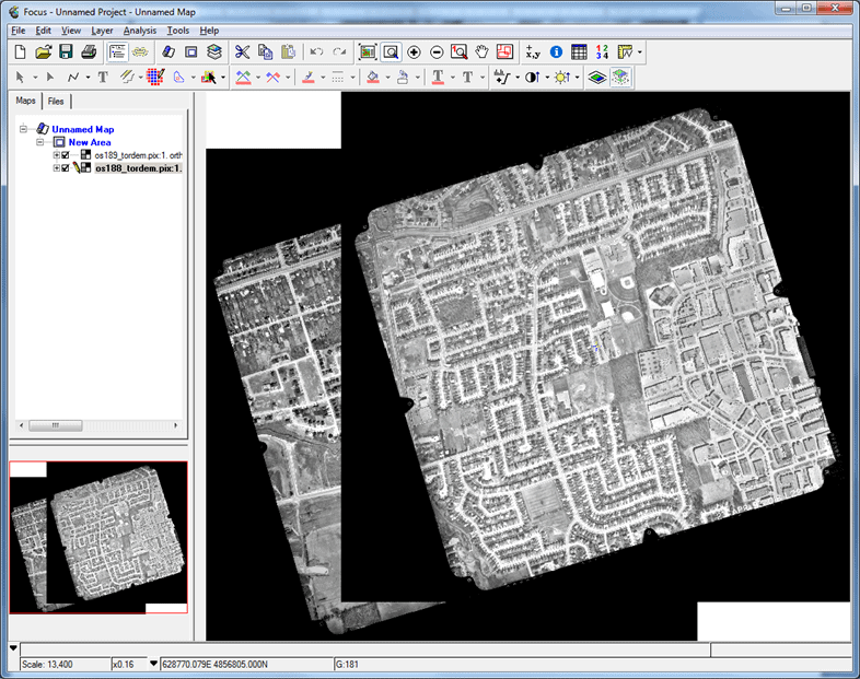
Found below is an example of a high-resolution airphoto of Richmond Hill, Ontario. This airphoto has been corrected using only an SRTM DEM. As a result, the ortho images do not align with each other.
The task of the TPS Model is to correct the overlap area of only one of the orthorectified images. When this correction is made, both orthos will overlap with each other. Areas outside the overlapped area will remain unchanged. This tutorial will show the steps taken to correct the misalignment between os188_tordem.pix and os189_dem.pix.
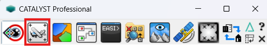
Open CATALYST Professional's OrthoEngine application
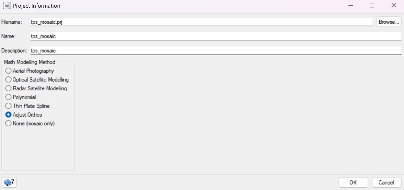
Start OrthoEngine and click ‘New’ on the File menu to start a new project. Give your project a ‘Filename’, ‘Name’ and ‘Description’.
Select ‘Adjust Orthos’ as the Math Modelling Method.
Click OK
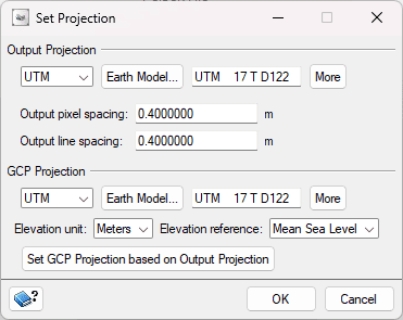
You can set up the projection information for the output files, the output pixel spacing, and the projection information of GCPs. Note: This window will automatically populate with the information from your images during the data ingest step. Update the information if required.
2. Data Input
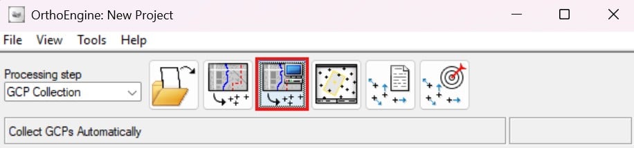
From the Processing Step drop-down list, select GCP Collection.
On the GCP Collection toolbar, click Open a new or existing image.
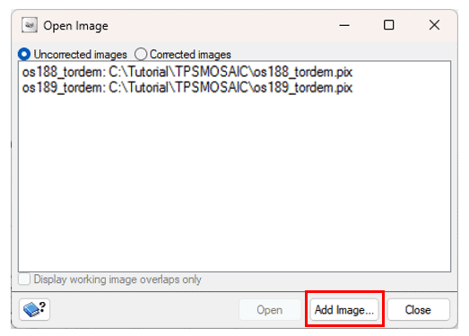
Click Add Image...
From the appropriate folder, select os_188_tordem.pix and os_189_tordem.pix.
Click Close. The two images are listed in the Open Image dialogue box. Note: You should save your project at this point. To save your project file, select “Save” from the “File” menu in the main OrthoEngine toolbar.
3. Collecting Ground Control Points Automatically
Automatic GCP collection allows you to collect several points and then manually remove points that are mismatched or not at ground level. Points at rooftops or building tops should be removed. The automatic GCP collection was modified for this tutorial so that most of the points collected are at ground level.
Note: Manual ground control points can also be collected for this project by selecting Collect GCPs Manually from the GCP Collection toolbar.
From the Processing Step drop-down list, select GCP Collection.
On the GCP Collection toolbar, click Collect GCPs Automatically. The Automatic GCP Collection dialogue box opens.
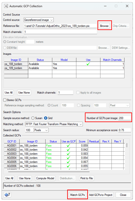
Click Browse next to Reference file. Navigate to os_189_tordem.pix
In the Number of GCPs per image field, enter 200.
In the Images table, click on Use > os_188_tordem.pix.
Click Match GCPs.
Click Add GCPs to Project.
Repeat the above steps for image os_188_tordem.pix.
Click Close.
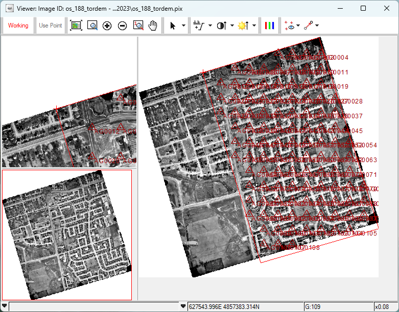
4. Viewing Collected GCPs
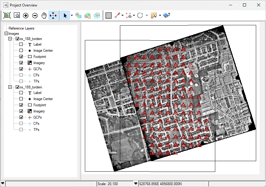
To view the result after automatic GCP collection, click on Display Project Overview
Right-click on the images and select Show > Footprint, Imagery and GCPs. You can also click on the + sign for each image and check the available items to display.
5. Defining Boundaries
Defining a binding polygon boundary is extremely important in the Adjust Orthos workflow, as any area outside of the polygon will not be modified. The polygon drawn should include all the GPCs collected for the image.
From the Processing Step drop-down list, select Geometric Correction. Click on Define Bounding polygon.
The Open Image and Define bounding polygon window opens.
Open one of the images.
Click the Individual Selection tool
Click on the red box in the Overview Window and move it across the image to adjust the polygon to include the area you want.
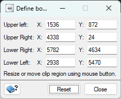
You can also input x and y values in the Upper Left, Upper Right, Lower Right, and Lower Left input boxes in the Define Bounding Polygon window.
6. Generating an Ortho
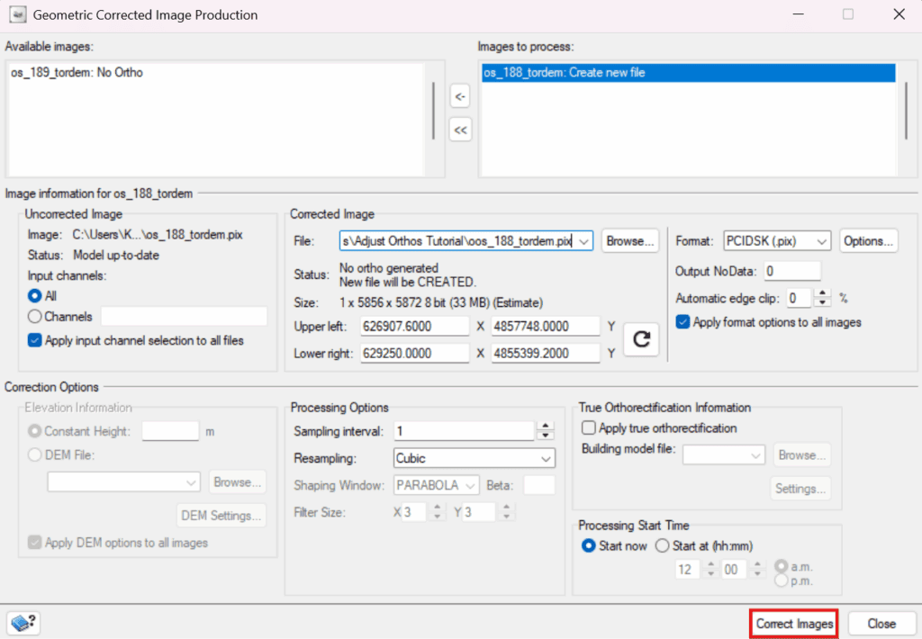
Still in the Geometric Correction Processing Step, click Schedule geometric correction. The Geometric Correction Image Production window opens
Move os_188_tordem.pix from Available images to Images to process.
Select Browse under Corrected Images and select a destination folder.
Select Cubic from the Resampling list options.
Select Correct Images from the Geometric Corrected Image Production window
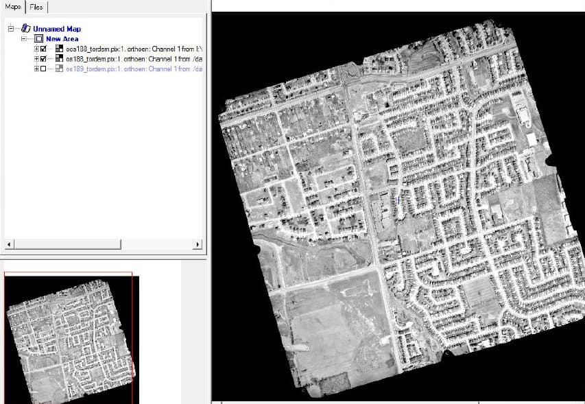
7. Viewing the Generated Ortho
The output new ortho generated is oos188_tordem.pix. In general, the result should be accurate at all the GCP locations.
Open Focus.
Open all 3 images to view the corrected alignment results oos188_tordem.pix, os188_tordem.pix, os189_tordem.pix.
Navigate to the folder where you stored the corrected image.
Manage Cookie Consent
To provide the best experiences, we use technologies like cookies to store and/or access device information. Consenting to these technologies will allow us to process data such as browsing behaviour or unique IDs on this site. Not consenting or withdrawing consent, may adversely affect certain features and functions.
Functional
Always active
The technical storage or access is strictly necessary for the legitimate purpose of enabling the use of a specific service explicitly requested by the subscriber or user, or for the sole purpose of carrying out the transmission of a communication over an electronic communications network.
Preferences
The technical storage or access is necessary for the legitimate purpose of storing preferences that are not requested by the subscriber or user.
Statistics
The technical storage or access that is used exclusively for statistical purposes.The technical storage or access that is used exclusively for anonymous statistical purposes. Without a subpoena, voluntary compliance on the part of your Internet Service Provider, or additional records from a third party, information stored or retrieved for this purpose alone cannot usually be used to identify you.
Marketing
The technical storage or access is required to create user profiles to send advertising, or to track the user on a website or across several websites for similar marketing purposes.