Geomatica Focus features the Smart GeoFill tool which allows you to alter aspects in your imagery, such as copying features or terrain elements, or filling an area of interest with content from an overlapping image to replace an unwanted aspect. You can adjust settings for blend width, color balance, contrast, and brightness of the source area to enhance or adjust its appearance in the destination layer.
There are two video tutorials available on the PCI Geomatics YouTube channel which outlines two Smart GeoFill workflows:
• Single Image Workflow: https://www.youtube.com/watch?v=0bBAIUBNoAY
• Multiple Images Workflow: https://www.youtube.com/watch?v=Bqc4VL987lY
The following tutorial outlines some common Smart GeoFill workflows:
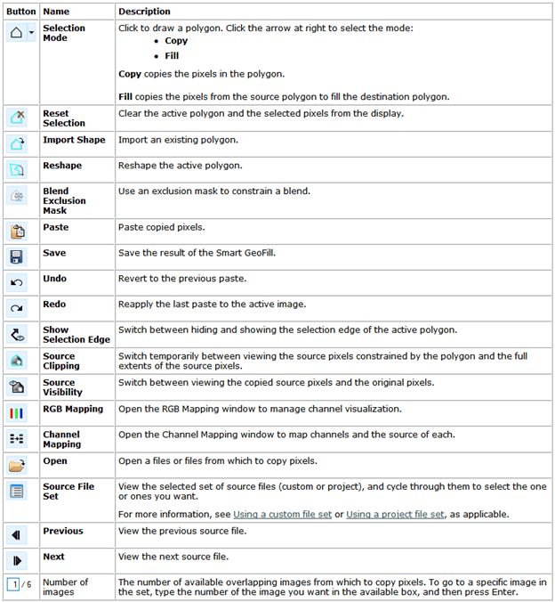
Smart GeoFill can be accessed through the Focus toolbar under the Tools dropdown menu. Information about the Smart GeoFill tool, including the following table is available from the Geomatica Help (Focus > Help > General): Geomatica Help > Focus > Image Processing > Using Smart Geofill
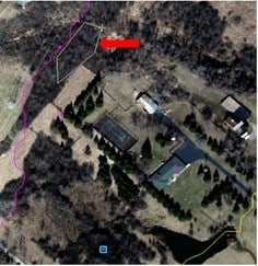
This workflow replaces pixels in an image with different pixels from the same image. This is useful if you do not have other overlapping images and there is an artifact in your image that needs to be removed. In this example, we will copy pixels from a different part of the image to remove a cloud.
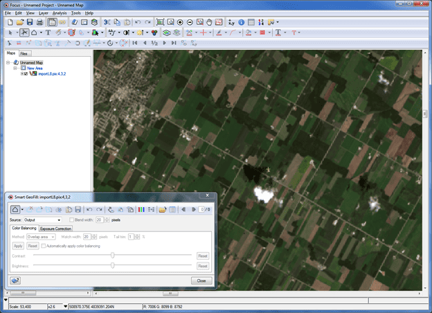
1. Open your image in Focus and then open the Smart GeoFill Tool (Tools > Smart GeoFill). We will be replacing the cloud and shadow with different pixels from the same image.
2. The Selection Mode button is automatically selected. With this tool selected you can create a polygon around the cloud in the image.

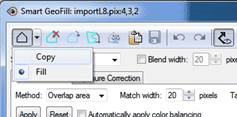
3. If you click on the Selection Mode button’s drop-down arrow you will notice there are two options: Copy and Fill. We want to leave this as the default In Fill mode, Smart GeoFill uses the concept of source and destination polygons. That is, you draw a polygon, to define the area you want to fill. This polygon is then designated as the destination polygon. In Copy mode, Smart GeoFill copies the pixels inside the polygon you have drawn (or selected), which you can then paste to suit.
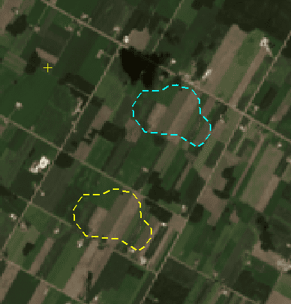
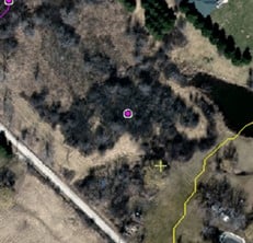
4. If you hover over the polygon, your pointer will switch to a four pointed arrow. You can click on the polygon and drag the source (yellow) polygon to choose the pixels that will fill the destination (blue) polygon. Try and choose pixels that are similar to your destination polygon.
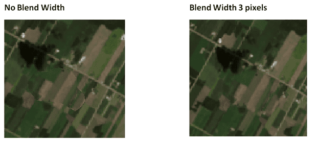
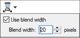
5. Hide the polygons ![]() to check if the edges match. You can check off Blend width box and set a blend value to blend the edge of the destination.
to check if the edges match. You can check off Blend width box and set a blend value to blend the edge of the destination. ![]()
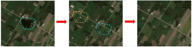
6. Once the filled section looks correct you can choose Paste
7. I will repeat these steps to remove the corresponding shadow.
8. Make sure to save the image once you have made your edits. ![]()
This workflow is a very common use for the Smart GeoFill tool. You can fix problem areas in your images by replacing the pixels in the problem area with pixels from a different image. This is particularly useful if you have an image with clouds. You can replace the cloudy section of the image with cloud free pixels from a different image.
1. Load the two images into Focus: Original image and cloud free image. In this example pixels from the cloud free image will be copied into the original image to replace the clouds in the original image.
2. Select the Original Image in the Focus Maps Tab
3. Open the Smart GeoFill tool (Tools > Smart GeoFill)
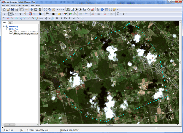
4. The Selection Mode button is automatically selected. With this tool selected you can create a polygon around the clouds in your image. I’m also making sure to create the polygon around the cloud’s shadows.
*Note: You can also import polygons from an existing vector layer. To do this, deselect the selection mode button from the Smart GeoFill window and select the polygon from your vector layer. You may need to click the Selection![]()
tool on the Focus toolbar. With the polygon selected, click Import Selected
![]()
from the Smart GeoFill window.
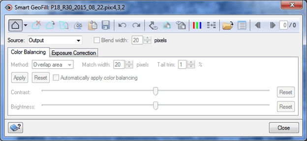
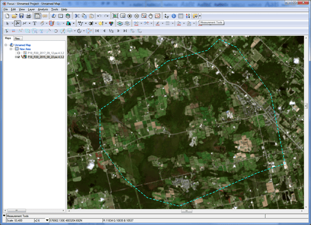
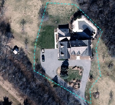
5. The dashed polygon is now visible on the image. In order to copy pixels from another image you will need to change the Smart GeoFill Source In this case we will switch this to Project File Set as we have already loaded the cloud free image into our Focus project.
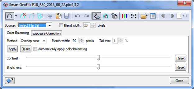
6. You will immediately notice that the pixels inside the polygon have been replaced by pixels from the cloud free image. However, at this point the colors do not match well.
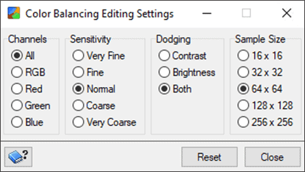
7. We can now adjust the colours of the copied pixels to match the original image. In many cases, clicking Automatically apply colour balancing will match the copied pixels. If required you can adjust the contrast and brightness manually using the sliders.
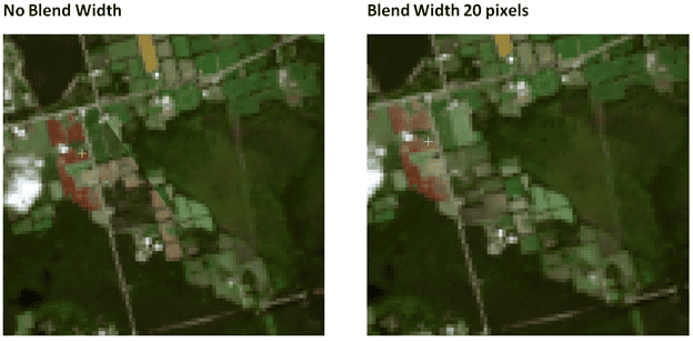
8. Before pasting the copied pixels you can turn off the vector ![]() to check how the pixels will look when copied. If the edges of the copied section are very obvious you can check off and adjust the Blend width.
to check how the pixels will look when copied. If the edges of the copied section are very obvious you can check off and adjust the Blend width. ![]()
9. When you are satisfied with the appearance of the copied pixels you can paste them to the original image ![]()
10. You will want to make sure to save the image so the edits are permanently applied before closing out of the Smart GeoFill window ![]()
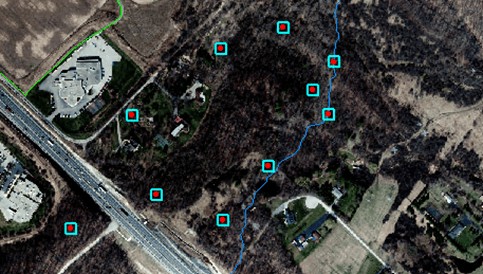
The Smart GeoFill tool allows you to load multiple images into a file set, draw a polygon and then compare all of the images to select the best pixels to copy.
1. Open the image that you wish to edit in Focus and then open the Smart GeoFill tool (Tools > Smart GeoFill).
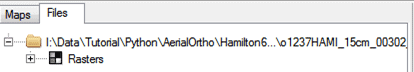
2. Only a single image is loaded into the Focus Files tab.
3. In the Smart GeoFill tool switch the Source to Custom File Set.
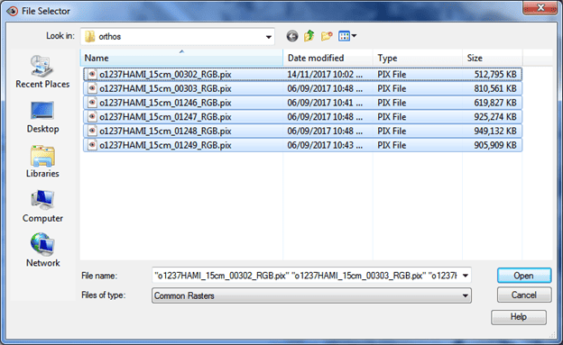
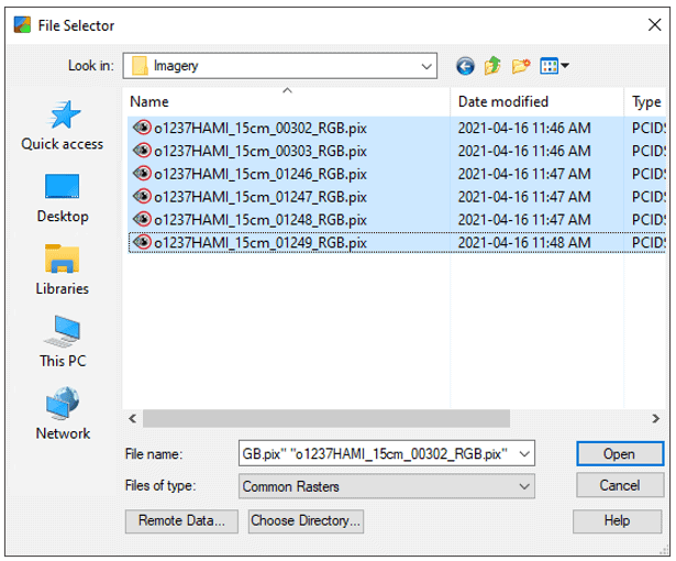
4. The File Selector window will open. Select and open all of the images from your stack.
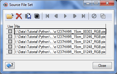
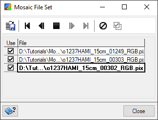
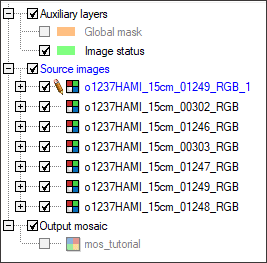
5. You can view all of the images that were added to the Smart GeoFill window from the Source File Set window ![]()
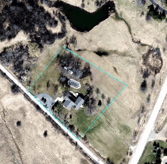
6. Click the Selection Mode button and draw a polygon around the area you wish to edit
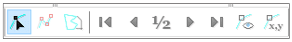
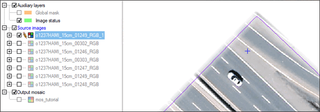
7. You will notice that the image selector arrows ![]() are available. Also if you open the Source File Set Window again the images that overlap with the polygon will be selected in the Use If there are images you wish to remove from the preview you can uncheck them in this column.
are available. Also if you open the Source File Set Window again the images that overlap with the polygon will be selected in the Use If there are images you wish to remove from the preview you can uncheck them in this column.
8. Use the selector arrows to navigate through each of the available images. As you navigate through the images, each of the images will be added into the Focus Maps tab. You will notice that the pixels in the polygon change to show the new pixels from the selected image. You can then choose which of the available images matches better with the surrounding pixels.
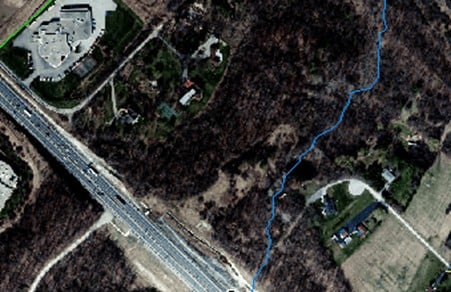
9. You can always click the Source Visibility button to view the original pixels.
10. Once you have chosen the best image, you can click paste to paste the pixels from the source image into your original image.
11. After completing the edit you can click the Reset Selection button to remove the polygon you were using. At this time, all of the source images are removed from the Focus Maps tab. Only the edited destination image remains.
12. Make sure to save the image once you have made your edits.
Note: If you are opening the New Project Wizard from OrthoEngine, the images will already be loaded, so you can proceed to Step 3 below.
Your first step in creating your mosaic is to select the source images you want. Source images consist of the raster data you want to mosaic. Typically, source images for a mosaic are:
It is good practice to first review the images to determine which ones are best (e.g., open them in Focus).
To add source images to the mosaic:
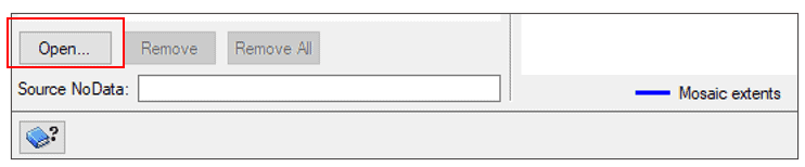
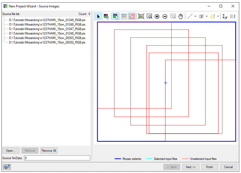

The New Project Wizard – Mosaic Definition window opens.
After you add the source images you want to use, your next step is to enter definition information about the output mosaic file.
To define the mosaic:
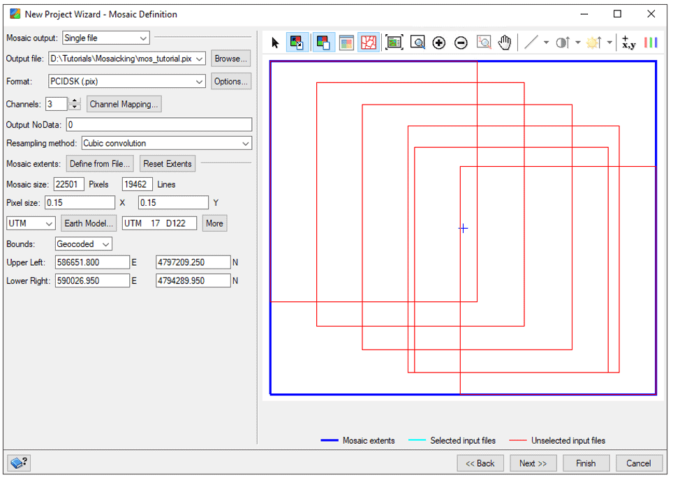
OPTIONS FOR MOSAIC DEFINITION
Mosaic output – Options for types of mosaic include:
Output file and Format – The Output file will be the file name of the final mosaic. The file extension you select will auto-populate the Format field. For example, <file_name>.pix or <file_name>.tif.
Channels and Channel mapping – The listed channel number is based on the source images. You can enter a different number of channels for the output mosaic (typically, to reduce number of channels) or map channels between the input and output images.
Output NoData – Enter one or more NoData values for the output imagery. For example, to specify NoData values for:
Resampling method – Options for resampling include:
Mosaic extents and Mosaic size – Change the extents by selecting a file from Define from file, or by dragging the blue Mosaic extents polygon in the viewer. If specifying a mosaic size (in Pixels and Lines), the Mosaic extents polygon will adjust automatically.
Projection Information – Specifies projection type (Pixel, UTM, Long/Lat, Meter, SPCS, or Other) and projection string.
Bounds and UL, LR coordinates – Specifies how to display the coordinates of the mosaic file:
The UL and LR coordinates can be adjusted based on coordinate system.

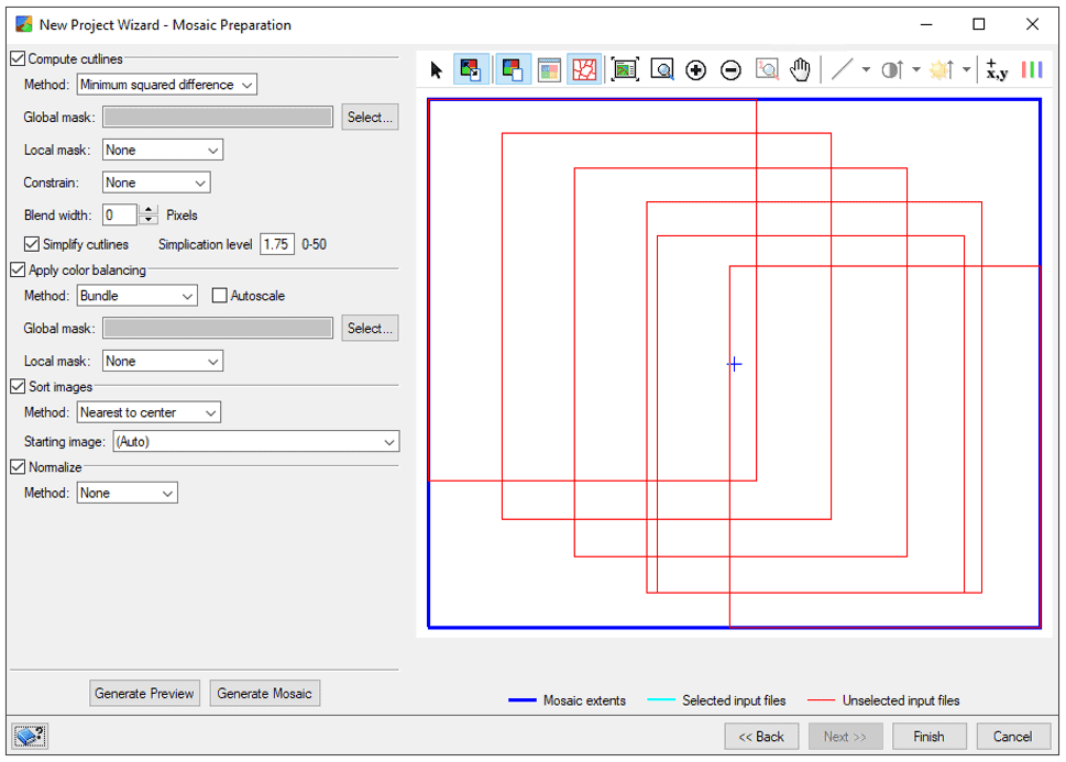
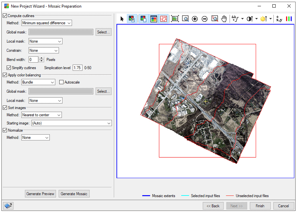
The New Project Wizard – Mosaic Preparation window opens.
Before you can generate a mosaic, you must first run mosaic preparation steps for the images that are added to the mosaic. This includes generating cutlines, applying colour balancing, determining sorting order, and applying normalization.
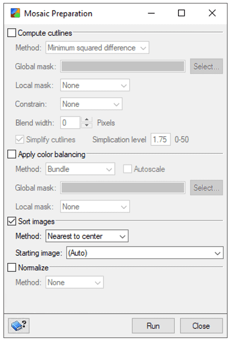
To prepare the mosaic:
OPTIONS FOR MOSAIC PREPARATION
Compute cutlines – Methods used to compute cutline polygons to use for the mosaic include:
Apply colour balancing – Evens out colour contrast from one image to another to reduce visibility of seams and produce a visually appealing mosaic. Methods include:
Sort images – Defines the order in which the images are added to the mosaic. Options include:
For more information on preparing a mosaic, click on the CATALYST Help button or search Setting up mosaic preparation in the CATALYST Help.
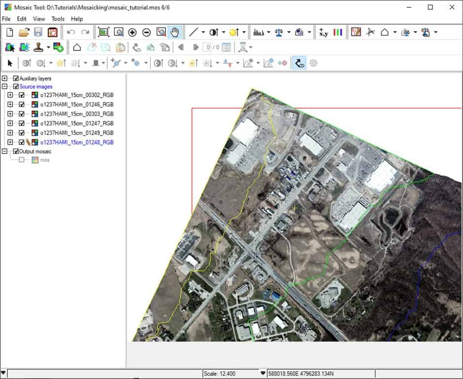
Once you click Finish, the New Project Wizard closes, and the project opens in Mosaic Tool.
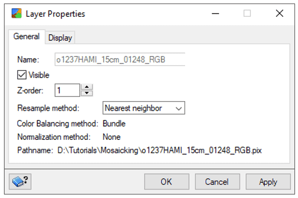
In the Mosaic Tool window, you can review and make changes to any mosaic project created with CATALYST software (i.e. the .MOS file). You can modify cutlines, colour balancing, normalization, or any other aspect to further improve the mosaic.
To open your mosaic project in Mosaic Tool:
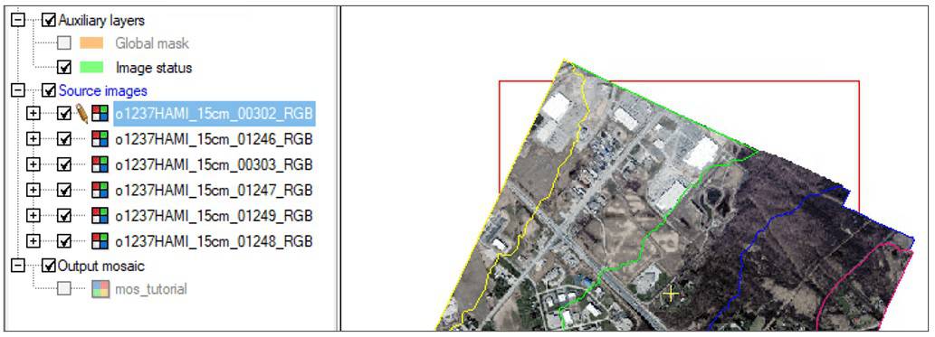
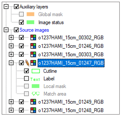
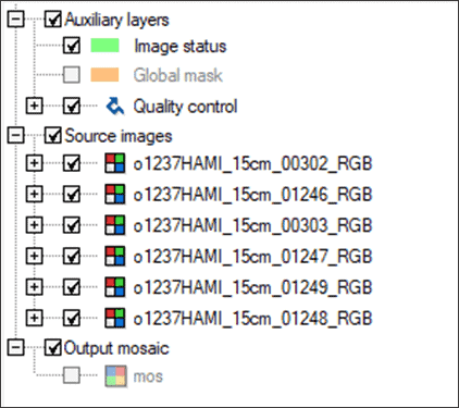
The order of the images, as shown in the Source images list in the control pane, is determined by the Sort method specified during Mosaic Preparation. The first image in the list indicates the top-most position in the mosaic.
To change the order of the images, do one of the following options:
iii. Click Apply, then OK.
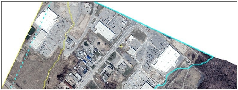
When creating a mosaic, you want to crop the images so the best portions are seamlessly joined together. You can adjust cutlines to ensure that seams between images are not as noticeable.
Good cutlines should avoid:
To edit a cutline:
Note: To add vertices to the cutline polygon, use the Add Vertices tool ![]()
. To move a specific vertex, select it with the Find tool and drag it to a new location.
Note: To individually recreate cutlines for a single image, right-click the image and choose Compute Cutlines.
Some images may contain patterns in visual brightness that could affect the seamless integration of the images into the mosaic. Normalization evens out bright and dark effects and can help to achieve a more pleasing mosaic. You can apply normalization to all the images or individual images in the Source images list.
OPTIONS FOR NORMALIZATION
None – Does not apply any normalization.
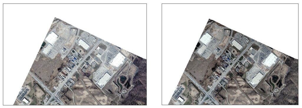
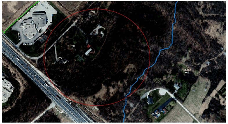
Hot spot normalization– A common distortion in aerial and optical-satellite images, caused by solar reflections, is called hot spot distortion. Hot spot normalization removes distortion from aerial and optical-satellite images, which often appear circular in imagery. It normalizes brightness over the image by fitting a Gaussian surface to the brightness values. Hot spot normalization does not remove smaller spot reflections from lakes, cars, and buildings.
Adaptive filter normalization – For images that have a large, irregular bright-and-dark patterns that cannot be modeled to a Gaussian surface. Patterns that model to a Gaussian surface are better handled by Hot spot. Adaptive filter normalization adjusts the brightness and contrast over local areas, thereby improving image detail, while reducing the bright-and-dark pattern over the entire image.
For more information, search Applying Normalization in CATALYST Help.
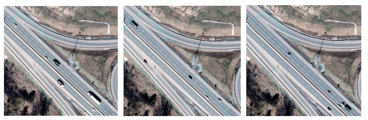
For example, the images below show before (left) and after (right) hot spot normalization.
To adjust normalization:
Radiometric differences between images can cause a patchwork effect in a mosaic. Colour balancing evens out the colour contrasts from one image to another to reduce the visibility of seams and produce a visually appealing mosaic.
When running Mosaic Preparation in the New Project Wizard, a colour balancing method was chosen (See Section 2.3). However, there may still be areas of the mosaic that need additional adjustments.
DODGING POINTS
A key concept in colour-balancing in a mosaic is the use of dodging points. A dodging point is a focal point on which you can make adjustments. You can add as many dodging points as necessary when adjusting the colour balance of an image to give you more precise control over the area to enhance.
Note: In order to make use of advanced colour balancing tools such as dodging points, you must apply the Bundle colour balancing method to your images.
To edit colour balancing:

OPTIONS FOR COLOR BALANCING
Tools to edit the entire image –
Tools to add dodging points –
Tools to edit the dodging points –
For more information on color balancing, click on the CATALYST Help button or search Performing colour balancing in CATALYST Help.
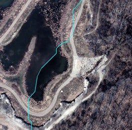
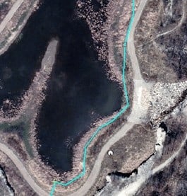
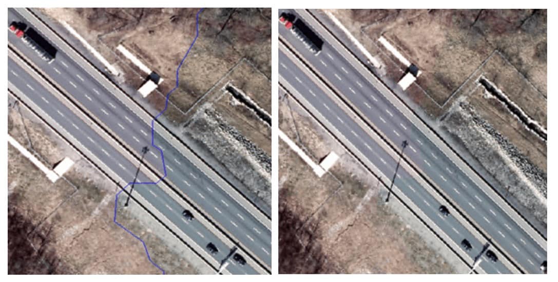
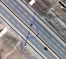
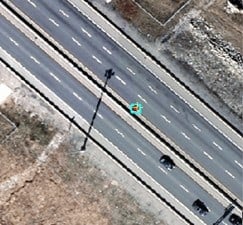
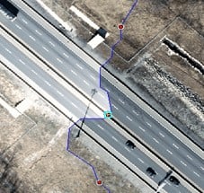
If you notice that the colour does not match well at the cutline between images, use edge dodging points to perform colour balancing. In this example, we balance the colour of a roadway along a cutline.
Note: To use edge dodging points, ensure Bundle is selected as the Colour Balancing method.
Note: To check the seamline between two images, toggle on and off the cutline with the Display All Cutlines ![]()
button.
To use edge dodging points:
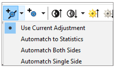
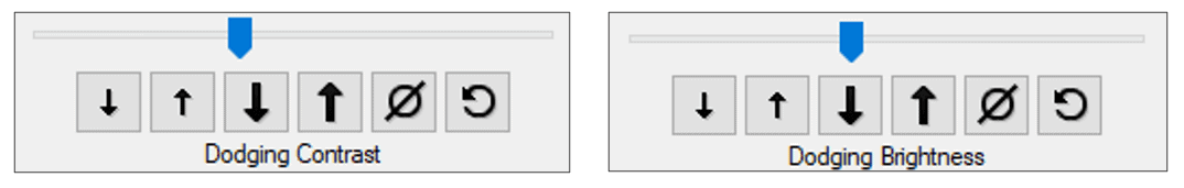
Note: Alternatively, instead of manually editing the brightness and contrast, click the Automatch Edge Point tool![]()
to adjust the image. From the drop-down, you can choose whether to adjust both images or the single image with the edge point.
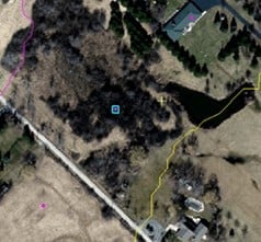
Floating dodging points can be used to adjust a specific section in the middle of an image. In this example, we increase the brightness of an underexposed section of forest.
To use floating dodging points:
Instead of simultaneously adjusting the red, green, and blue (RGB) channels – or the bands assigned to these channels – you can further control how to balance colour using dodging points.
To adjust the brightness/contrast of a specific band:
To compute and store regional colour-balancing statistics, use the Store Statistics
![]() and Automatch to Statistics
and Automatch to Statistics![]()
buttons. The region you select can be a point, a rectangle, or a polygon. When you apply the stored statistics to any other dodging point, the colour balancing of the region of stored statistics is applied.
To store the adjustment statistics:
Note: Once your automatch is set, you can further improve the colour by changing brightness and contrast.
The Mosaic GeoFill tool allows users to alter aspects of their imagery, such as filling an AOI with content from an overlapping image to replace an unwanted aspect. Pixels are copied from the overlapping image and pasted to a new source images layer (called overlapping image_1). For example, you can use Mosaic GeoFill to replace clouds in an AOI with cloud-free pixels from any image in the Source images list that overlaps the AOI.
The Mosaic GeoFill tools can be found on the Mosaic Tool Toolbar.

For more information about the functionality of each tool in the Mosaic GeoFill Toolbar, search About the Mosaic GeoFill toolbar in CATALYST Help.
A polygon is a vector element you draw on top of the image around the AOI: in this case, an area you want to repair. You draw a polygon by using a node-to-node selection technique where you click a starting node, and then progressively click to add each additional node to form the polygon you want according to the shape of the AOI.
To draw a polygon:
Note: To cancel the polygon at any point while drawing it, press the Esc key. This will cancel and unselect the GeoFill Polygon drawing tool.
Note: To redraw your polygon, you can use the Reset Selection tool ![]() to delete the currently drawn polygon. You will notice the polygon and copied pixels will be removed from the display.
to delete the currently drawn polygon. You will notice the polygon and copied pixels will be removed from the display.
You may need to reshape your polygon to include a large or smaller AOI.
To reshape a polygon:
Now that the AOI polygon has been drawn, you can view all the available images to choose the preferred alternative pixels to fill the polygon area.
To copy new pixels into the polygon, you have 3 options:
The blending tool allows you to control blending or smoothing of pixels around the perimeter of pixels to be pasted. A blending zone is defined as half the specified blend width, on either side of the edge of the GeoFill polygon. New pixel values in that zone are computed by combining original with copied pixel values.
Note: In areas containing bright or significantly different features, setting blend width too high may cause “ghosting” or “doubling” of features.
To smooth the perimeter of copied pixels:
Once you are ready to commit the changes you’ve made using Mosaic GeoFill, paste the new pixels into the source image.
To commit the changes:
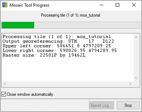
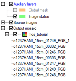
The final step in the mosaic generation process is to add the edited source images to the defined mosaic. From your source images, you have the option to add all the images or individual images to the final mosaic file.
To add all the images from the Source Images list:
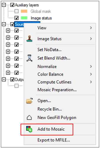
To add individual images from the Source images list:
After generating the mosaic file, you can choose to restore and reprocess any of the images if you notice a problem in the mosaic.
To restore the images:
Additional optional tools can be used in your mosaic project, particularly when working with larger mosaics that require verification from multiple users. The tools shown below include defining a working area of the mosaic and conducting quality control and verification.
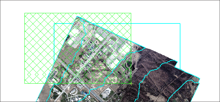
The Mosaic Overview window is helpful when working with large projects. You can easily examine the entire mosaic to identify areas to modify, then select the images and open them in the Mosaic Tool window. See the diagram below to see the elements of the Mosaic Overview window, including a working area.
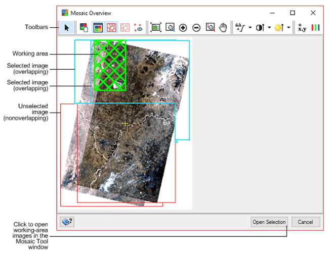
A working area is an extent of images you want to display and modify in the Mosaic Tool window. All of the data from the overlapping images you select will be displayed.
Note: There are a number of options available from Mosaic Tool > Tools > Options. A particularly useful option is Performance – Bypass Mosaic Overview. When opening a large mosaic project, the mosaic overview window will open instead of automatically loading all images into Mosaic Tool (which can be time-consuming). You can make an image threshold at which the Mosaic Overview window appears when you open a mosaic project.
To open the Mosaic Overview window:
 . The Mosaic Overview window opens with all images selected.
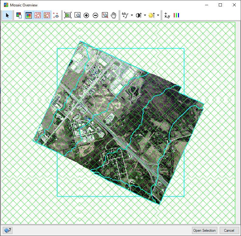
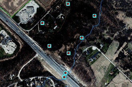
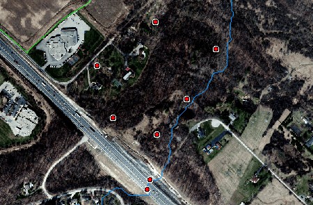
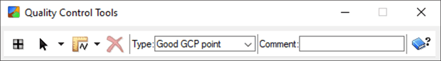
Potential problems in the mosaic can be identified and flagged using the Quality control layer along with reference vectors and the mosaic preview. These problems can then be addressed before generating the final output mosaic.
To create a quality control layer:
 icon.
icon.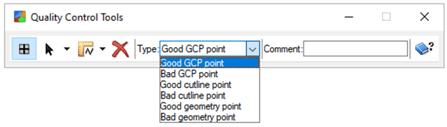
The verification tool is particularly useful with a larger mosaic. Once you have performed quality control on an image of your mosaic, you can change the status to reflect the verification progress. Typically, this is to change the status to Verified from the default, Unverified. Assigning a status helps you keep track of images you have and have not modified.
To use the verification tool:
 .
.