Home » Tutorials » Change Detection and Area Reporting
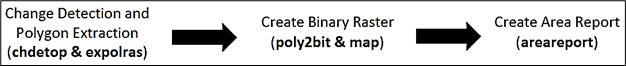
This tutorial outlines how to detect changes between two images using CATALYST Professional, and then create an area report stating the percentage and total area of change. It is a step-by-step guide for using the CATALYST change detection with the algorithms CHDETOP, EXPOLRAS, POLY2BIT, MAP, and AREAREPORT.
CHDETOP - Detects differences between two input raster images ("new" and "reference"). Typically, the function is used on a pair of images from the same optical satellite sensor and depending on the sensor.
EXPOLRAS - Converts an input raster image to a binary image using a specified threshold value, then extracts polygons from the resulting binary image and filters them based on area and compactness values.
POLY2BIT - Converts a polygon layer to a bitmap layer.
MAP - Provides encoding of bitmaps into an image channel using a user-defined constant as a gray level.
AREAREPORT - Calculates the total area for each pixel value in a raster image and generates a report.
Tutorial data description: The reference data is a Landsat-5 TM image captured in 1990 of the Prince George area in Northern British Columbia, Canada. This area is well known for the logging activities that occur there. The image is used as reference in order to perform change detection, which in this case is to identify vegetation loss (i.e., deforestation).
The data used in the tutorial can be accessed from HERE.
To start, create a CATALYST Professional Focus project (.gpr) file in which to save your output layers.
To create a Focus project (.gpr) file:
From the CATALYST Professional toolbar, open Focus.
Load your new image and reference image into Focus: First, click on the Maps tab, and then drag and drop the files into the Maps panel.
For this tutorial, the new image is 4922_etm_12sep1999_enh.pix and the reference image is 4922_tm_12aug1990_enh.pix.
Go to File > Save Project As. Name your project and save it in your working folder.
To begin change detection:
With your images still loaded in Focus, click on Tools > Algorithm Librarian.
Search for and open the CHDETOP algorithm, titled “CHDETOP: Optical Change Detection”.
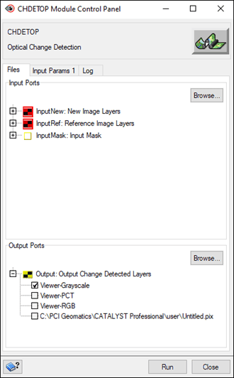
The CHDETOP Module Control Panel opens with the Files tab active.
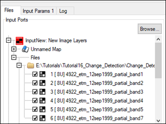
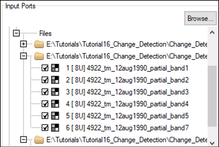
Under Input Ports, expand the InputNew tree branch to add the layers of the more recent image.
Select all 6 channels from the new image. For this tutorial, select the 1999 image.
Retract the InputNew branch and expand the InputRef branch to add the layers for the older image, i.e., the reference image.
Select all 6 channels from the reference image. For this tutorial, select the 1990 image.
Retract the InputRef branch.
In the Output Ports section:
Uncheck the Viewer-Grayscale.
Check C:\PCI Geomatics...\Untitled.pix.
Click the Browse button for Output Ports. In File Selector, navigate to your working folder and name the output file, e.g., Output_CHDETOP.pix.
Click Save.
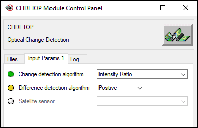
Click on the Input Params 1 tab.
Change the Change detection algorithm to Intensity Ratio.
Click Run.
Once the algorithm has finished running, close the module window and minimize Algorithm Librarian.
Note: The output file is automatically added to the Focus project.
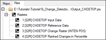
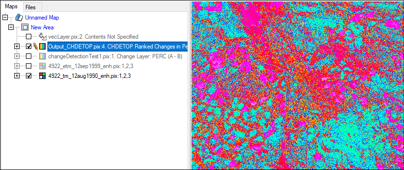
In Focus, click on the Files tab. Expand the branch for the top file. This is the output file that was just created using CHDETOP:
Description of CHDETOP output
The output change detection file contains 4 channels: Input Data: A SPANS channel showing an averaged image of the input 6 bands from the new image. Reference Data: A SPANS channel showing an averaged image of the reference 6 bands from the reference image. Change Raster (INTEN POS): The absolute values of change, as per the intensity ratio algorithm. Ranked Changes in Percentile: A raster that ranks change based on percentiles (relative change). We will be using this channel for identifying and extracting polygons of deforestation.
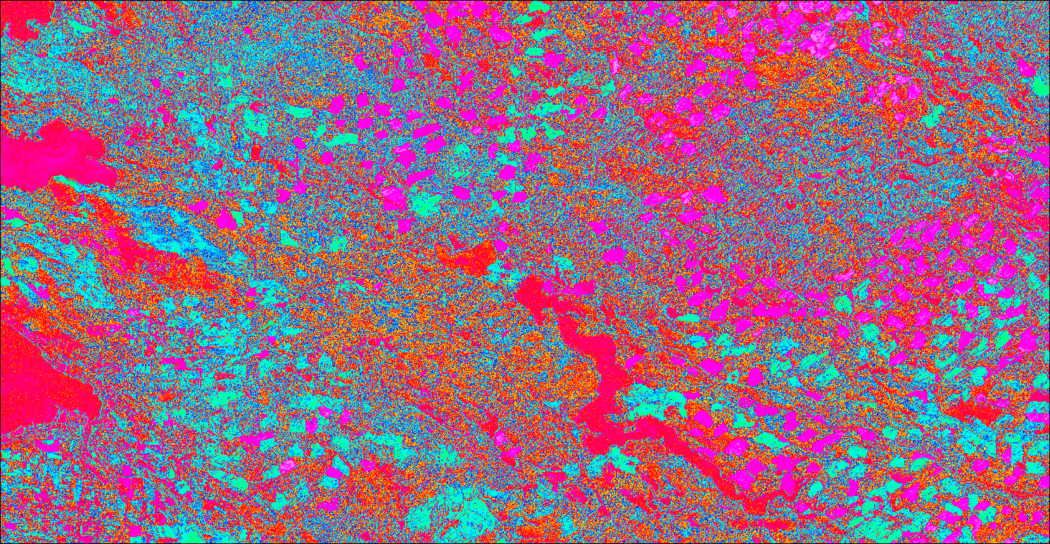
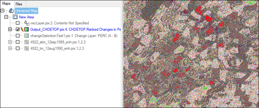
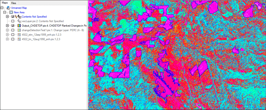
Right click on Channel 4: Ranked Changes in Percentile and select View > As Pseudocolor.
The change image loads into Focus.
Optionally, you can play with the PCT settings for your preferred visualization of the data (right-click Change Layer > Edit PCT > select Smooth):
Toggle this layer and the reference image layer on and off to show the deforestation change. In this visualization, change between images is visible in blue while pink represents no change.
2. Extracting change as polygons - EXPOLRAS
EXPOLRAS converts an input raster image to a binary image using a specified threshold value, extracts polygons from the resulting binary image, and then filters them based on area and compactness values. Finally, it outputs results to a vector layer.
To extract change as polygons:
In Focus, go to Tools > Algorithm Librarian.
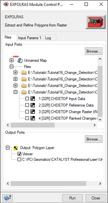
Navigate to the EXPOLRAS algorithm, titled “EXPOLRAS: Extract and Refine Polygons from Raster.”
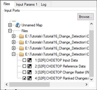
In the Files tab, click Channel 4: Ranked Changes in Percentiles from the CHDETOP output file.
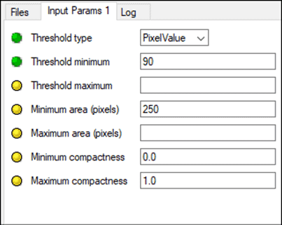
Click Input Params 1 tab:
Set the Threshold minimum value to 90.
Set the Minimum area (pixels) to 250.
Leave all other values as default.
Click Run.
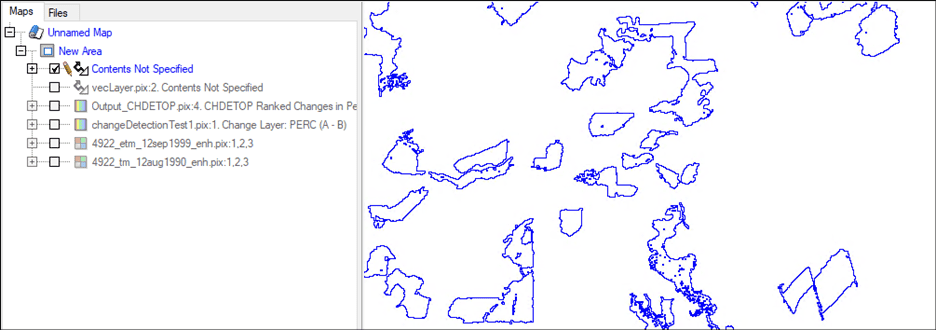
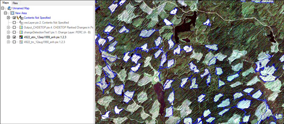
Once the process has completed, the polygons will automatically be rendered in the viewer. Close the EXPOLRAS module and Algorithm Librarian.
In Focus, zoom to 1:1 resolution. a. Toggle the Ranked Changes in Percentile layer off.
As you can see, the polygons outline the areas where deforestation has occurred. This can be observed by toggling the newer image raster on and off.
3. Converting polygon layer to bitmap - POLY2BIT & MAP
Next, we need to create a binary raster from the polygons. This binary raster will be required to run an area report.
To create a binary raster from the polygons:
With your project open in Focus, go to Tools > Algorithm Librarian.
Search for the POLY2BIT algorithm, titled “POLY2BIT: Convert a polygon layer to a bitmap layer.”
Under the Files tab:
For Input: Polygon Layer, choose your EXPOLRAS vector layer.
For InputArea: Bounding Area, choose the georeferencing segment for the same vector file.
Under Output Ports, leave Viewer checked. Also select the directory, and click Browse give your output bitmap a name and location, e.g., Output_POLY2BIT.pix.
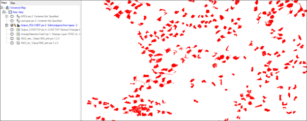
Click Run.
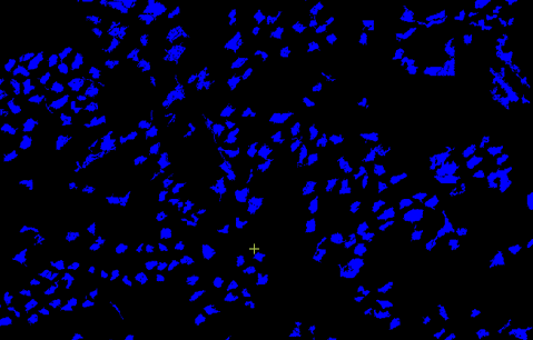
The output will appear in the Focus viewer:
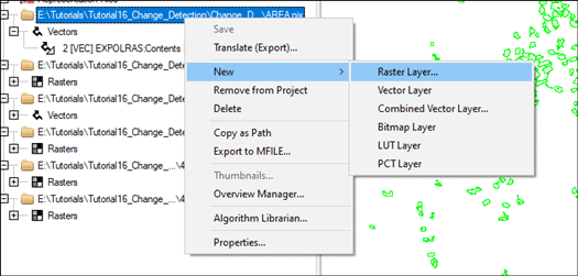
To create an empty 8-bit raster channel, right-click the filename > New > Raster Layer. Choose 1 8-bit unsigned (8U) layer. Rename it, if desired.
Run the MAP algorithm. From Algorithm Librarian, find “MAP: Database Bitmap to Channel Encoding”.
Under the Files tab: a. For Input: Image Layer, select the empty 8U raster channel you just created. b. For InputBIT: Bitmap Layer, select the output file from POLY2BIT.
Under Output Ports, leave Viewer checked. Also select the directory, and click Browse give your output bitmap a name and location, e.g., Output_MAP.pix.
Under the Input Params 1 tab, set Gray Level Value List (Max. 16) = 1.
Click Run.
Now you have a raster layer with values of 1 and 0, marking change and no change, respectively. Use that as input for the area report.
4. Generating an area report - AREAREPORT
The area report of the change detection and extract polygon algorithms can be created for identifying and extracting other forms of change (i.e. new vegetation).
To generate an area report:
Go to Tools > Algorithm Librarian.
Navigate to and open the AREAREPORT algorithm.
In the Files tab, expand the Files tree branch and select the raster channel created as the output of the MAP algorithm, e.g., Output_MAP.pix.
Click on the Input Params 1 tab, and change Reporting Units to any unit that makes the most sense for your area, e.g., Square Kilometres.
Click Run.
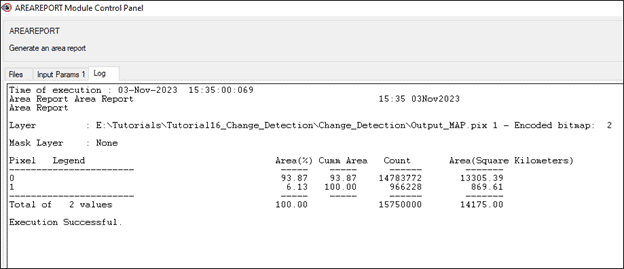
After the progress bar disappears, click on the Log tab in the AREAREPORT Module Control Panel window.
Description: The log below shows the total area that has been deforested, Area (Square kilometres), as well as a relative measure, Area (%).
Manage Cookie Consent
To provide the best experiences, we use technologies like cookies to store and/or access device information. Consenting to these technologies will allow us to process data such as browsing behaviour or unique IDs on this site. Not consenting or withdrawing consent, may adversely affect certain features and functions.
Functional
Always active
The technical storage or access is strictly necessary for the legitimate purpose of enabling the use of a specific service explicitly requested by the subscriber or user, or for the sole purpose of carrying out the transmission of a communication over an electronic communications network.
Preferences
The technical storage or access is necessary for the legitimate purpose of storing preferences that are not requested by the subscriber or user.
Statistics
The technical storage or access that is used exclusively for statistical purposes.The technical storage or access that is used exclusively for anonymous statistical purposes. Without a subpoena, voluntary compliance on the part of your Internet Service Provider, or additional records from a third party, information stored or retrieved for this purpose alone cannot usually be used to identify you.
Marketing
The technical storage or access is required to create user profiles to send advertising, or to track the user on a website or across several websites for similar marketing purposes.