Aerial triangulation (AT) computes the positioning and orientation of each image, and accounts for known optical distortions. To perform AT, ground control points (GCP), tie points (TP), or both are required.
A GCP is a point with known ground coordinates used to determine the relationship between an image and the ground. In CATALYST Enterprise, GCPs can originate from a number of sources, such as the Global Positioning System (GPS), ground surveys, geocoded images, vectors, topographic maps, or from a chip database. CATALYST Enterprise can also collect stereo GCPs from geocoded images.
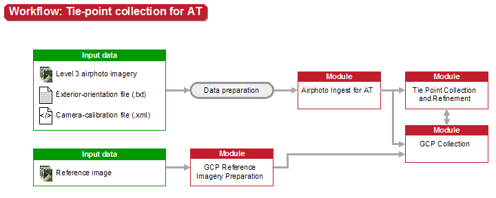
To collect stereo GCPs, you use the GCP Reference Imagery Preparation module and the GCP Collection module. The GCP Reference Imagery Preparation module prepares the geocoded imagery and determines GCP candidates. You then use the GCP Collection module to collect stereo GCPs from the prepared geocoded imagery.
A TP is a point with no known ground coordinates and is used to improve the alignment between images. In CATALYST Enterprise, TPs are created with the Tie-Point Collection and Refinement module.
After collecting the points and completing the AT, you can perform a variety of quality-control (QC) tasks, as described in the following table.
| To | See |
|---|---|
|
Quality control with CATALYST Professional OrthoEngine |
|
Determining error estimates for position and orientation |
|
Third-party software and aerial-triangulation workflow |
After performing QC tasks, you can, if necessary, repeat one or more steps of the AT workflow. If you do so, use the most recent OrthoEngine project file as input for each module or modules, and then follow the AT workflow.
For more information, see: