Parameter descriptions
InputPRJ: Input OrthoEngine project file
The name of the input CATALYST Professional OrthoEngine project file or a text file in which each line is the path and file name of an OrthoEngine project. When you specify two or more OrthoEngine projects, they are merged into a single project to perform TP matching.
Images in the input project file or files must have an approximate math model, based on either existing information in the math-model segment or the orbit segment.
When your input is several projects, which are merged subsequently, the images must have a one-to-one mapping with photo ID. That is, a single image file referenced in more than one project must have the same photo ID in all projects, and the photo ID must be unique to that one image file.
Output: Output OrthoEngine project file
The name of the OrthoEngine project file to which to write the TPs collected automatically by AUTOTIE .
Working image set
The processing method to use for overlapping images.
- All images: TPs are measured for each pair of overlapped images.
- Specify image ID: TPs are measured for images based on the image IDs you specify. When you select this option, you must enter image IDs for Image IDs .
- Project overlap: When your input is several projects, which are merged subsequently, AUTOTIE measures only overlaps spanning various projects. This is useful when the same image pair occurs in more than one project and already has TPs in the original project.
Image IDs
Available only when you select Specify image IDs in the Working image set list, enter the image IDs as one or more comma-delimited values; for example: 'IMAGES SPOTLEFT,SPOTRIGHT' . TPs are measured for all overlaps involving at least one of the specified images, including overlaps between images specified in the image set. If necessary, you can enter only a single image ID, such as 'IMAGES SPOTLEFT' .
LOCLMASK
Specify whether to apply a local mask to prevent points from being collected in those locations. If no value is specified for this parameter (default), or you specify a value, but one or more of the images do not contain a bitmap or vector segment, no local exclusion mask will be applied for those images.
LOCLMASK = (NONE | BIT | VEC | <n>)
- NONE: exclude no pixels from the computation
- BIT: use when there are bitmap segments in at least some of the image files that define exclusion regions. When one of the images contains multiple bitmaps, the last one is used. All image pixels covered by the bitmap are excluded from point collection.
- VEC: use when there are vector segments in at least some of the source image files that define exclusion regions. When one of the source images contains multiple vector segments, the last one is used. This vector segment must be a polygon, and all image pixels enclosed by the polygon are excluded from point collection.
- <n>: specifies a particular segment number that contains the desired mask segment to be used.
This parameter is optional.
Existing tie point rule
The rule to apply for processing existing TPs in the input project or projects.
- Replace existing tie points (REPLACE): Remove the existing TPs in the input project and replace them with those newly measured.
- Add existing tie points (ADD): Add new TPs to the input project that contains existing TPs.
Matching channels: Input image channels
The channel or channels in the input image file to use for matching TPs in a pair of images. When you specify two or more channels, averaging is used to determine matching.
InputDEM: Input elevation channel
The channel that contains the digital elevation model (DEM).
Elevation background value
The background elevation (NoData) value of the input DEM. Areas that are defined as NoData in the DEM are excluded from consideration while searching for TPs.
If no value is specified for this parameter, AUTOTIE scans for ELEVATION_BACKGROUND or NO_DATA_VALUE metadata tags, first at the channel level, and then at the file level. If this value is neither specified nor found in the metadata, a default value of -32768 is used.
Elevation reference
The vertical reference for the elevation values in the source DEM, or for the constant Elevation Offset and Elevation Scale ( ELFACTOR ) value or values, if defined.
Elevation units and accuracy
The unit of measure for the elevation values of the input DEM file. If necessary, you can specify the second value as the vertical accuracy of the DEM to use for TP collection. This DEM will also be used during TP collection by changing the TPs to elevation TPs.
- METER
- FEET
- US_FEET
- METER, 15
If elevation values are specified by using FEET , the conversion factor to meters is 0.3048 (corresponding to International Feet). With US_FEET , the conversion factor to meters is 1200/3937 (corresponding to U.S. Survey Feet).
If no value is specified for this parameter, AUTOTIE scans for an ELEVATION_UNITS metadata tag at the file level, and then again at the channel level. If this value is neither specified for the parameter nor found in the metadata, METER is applied.
Elevation offset
The elevation offset used by the DEM.
If no value is specified for this parameter, AUTOTIE scans for an ELEVATION_OFFSET metadata tag at the file level, and then again at the channel level. If this value is neither specified for the parameter nor found in the metadata, a value of 0.0 is used, indicating that there is no offset.
Elevation scale
The elevation scale used by the DEM.
If no value is specified for parameter, AUTOTIE scans for an ELEVATION_SCALE metadata tag at the file level, and then again at the channel level. If this value is neither specified for the parameter nor found in the metadata, a value of 1.0 is used, indicating that the scale is one to one.
Search Source Method
The source of sample points for matching TPs. Sample points may be generated automatically by using the SUSAN or GRID option, or they can be specified explicitly in a sample file.
- SUSAN: Sample points are generated automatically by using the Susan corner-detection algorithm.
- GRID: Sample points are generated automatically by using sample points distributed evenly across the overlap region.
The SUSAN and GRID options determine how to find the initial candidate positions in one image—the source image—for collecting sample points. AUTOTIE builds a patch around each candidate position for which it searches in overlapping images.
- The SUSAN option finds the candidates by running a corner-detection algorithm on the image, which looks for corner-like features to use as candidates.
- The GRID option creates candidates in a grid-like pattern. Because this option does not preprocess the image, it tends to be faster, but it may find fewer matches because the grid point might fall on a featureless flat patch somewhere in the image that cannot be matched to anything in the overlapping images.
When collecting TPs, the SUSAN option is often preferred, because it facilitates performing quality assurance on the collected TPs; that is, you can visualize a recognizable feature (a building corner or specific tree, for example) and look at another image to see if it matches correctly.
Number of points per area
The number of sample points to use for matching TPs in the specified distribution area ( Distribution ) according to the value specified for Search source method . If Distribution is Entire or Overlap , the default value is 64 or 25 , respectively.
Number of trials per point
The total number of trials for each point before giving up on the match. AUTOTIE attempts to match the primary sample point and, if that fails to match, a secondary point will be chosen within the same grid cell as an additional sample. Possible values are integers between 1 and 5 The default value is 1 .
Edge margin distance
The minimum distance, in pixels, between the edge of the image and the placement of the candidates.
The edges of the candidate grid will be the number of pixels you specify from the edge of the image.
If no margin is specified, it will be calculated automatically as five percent of the overlap dimension or 256 pixels whichever is less.
Distribution: Area of distribution
The area of each image in which to distribute the number of TPs per Number of points per area and the method selected for Search source method .
-
ENTIRE: evenly distributes TPs in the entire image being matched. The number of samples is multiplied by the overlap percentage and the density of candidate distribution is relatively constant. ENTIRE is used typically with aerial imagery.
Figure 1. Distribution with ENTIRE using a value of 9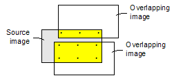
-
OVERLAP: evenly distributes TPs only in the area that overlaps the adjacent image. OVERLAP: is used typically with satellite imagery in which the overlapping areas may be less regular than in aerial imagery. Smaller overlaps provide a distribution of candidates that is more dense.
Figure 2. Distribution with OVERLAP using a value of 10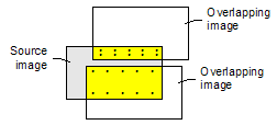
Matching method
The algorithm used for automated matching of TPs.
- FFTP: Fast Fourier Transform Phase Matching: When two images have a relative shift between them, the result is a phase difference in the Fourier domain. FFTP determines the shift between images using this phase difference.
- NCC: Normalized Cross-Correlation: This method finds the relative shift between two images by finding the shift that produces the maximum cross-correlation coefficient of the gray values in the images.
If no value is specified for this parameter, FFTP: Fast Fourier Transform Phase Matching is used by default.
When the two images being matched have similar gray values and appearances, NCC generally produces acceptable results. When there is a rotation or image-size error in the initial math models, NCC may produce better matching results than FFTP. Because the template size that NCC uses is smaller than that of FFTP, NCC also typically generates faster results.
For more consistently accurate results, one of the FFTP-based methods is recommended. An FFTP-based method uses a larger template size than NCC and, because it works in the frequency domain, it looks at the patterns of details in the image rather than the gray values in a small neighborhood, which NCC uses. This makes it more robust than NCC when there is a large difference in brightness between images or when a major land-use change has occurred. FFTP-based methods also better match images of the same area from different sensors or spectral bands.
Search radius
The size of the area to search in a target image. The unit of measure for this value is determined by the value of Search radius units ( SEARCHUN ).
Matching candidate points in the source image are projected to the ground, and then reprojected to the target image. You must have a good initial position for the two correlation windows. With an aerial project, a good initial position can be determined when the exterior orientation (EO) parameters of the images are accurate.
- If the contrast of the images is very low or very high, AUTOTIE may not be able to determine the correlation. Make sure the images have an appropriate level of contrast.
-
If the search radius is too small, too few TPs may be collected, and if the initial position information is inaccurate, or there is a large amount of terrain relief, the TPs may be distributed unevenly. Be sure to use a search radius of an appropriate size. A larger search radius will increase processing time, however.
Tip: To quickly determine an appropriate search radius, generate two coarse orthorectified images by using an average constant-elevation value, and then determine the greatest offset for the same feature point in the overlapping images. You can use the offset, plus a certain amount of buffer, as a reference for the search radius to use in collecting TPs.
The search radius specifies the distance from a starting location on the target image over which to conduct the search for the best match with a fixed point on the source image.
The search radius is also an estimation of error with the positional information of the raw image and the accuracy of the DEM. If you know that your images are accurate to 80 meters, and your DEM is accurate to 200 meters, set the search radius to 280 meters. A larger search radius—for example, 300 or greater is recommended for hilly or mountainous terrain—will require more processing time, because more locations are evaluated to determine the best match for a TP.
If no value is specified for this parameter, AUTOTIE uses a default search radius of 100 pixels.
Search radius units
The unit of measure of the value of Search radius ( SEARCHR ).
- PIXEL: search radius in pixels
- METER: search radius in meters
- FEET: search radius in feet
- US_FEET: search radius in U.S. Survey feet
With PIXEL , the value is interpreted as the number of pixels in the reference image. With METER , FEET , or US_FEET , the search radius represents meters or feet in the reference image.
Minimum acceptance score
The threshold value to use to control acceptance or rejection of a candidate TP as valid. The value is the minimum match quality to consider as an acceptable match, with 1.0 indicating a perfect match.
When using the FFTP matching method, the value is converted internally to a minimum-acceptable value for peak phase-shift.
When using the NCC matching method, the value specifies the minimum match score required to accept a local match between the input and reference images as a TP. The default value is 0.75 .
Report
Specifies where to direct the generated report.
Available options are:
- LOG: generates a report on the terminal (default)
- <modulename.RPT>: appends a report to the module's RPT file
- DISK: generates a report on file "IMPRPT.LST"