Parameter descriptions
MFILE
The name of an image file, a folder, or a text file that contains the input images to process.
For information about basic use of an MFILE with CATALYST Professional algorithms, see Using an MFILE with a CATALYST Professional algorithm.
When you specify multiple files for MFILE, by using a text-file list or a wildcard, ORTHO prefixes the output files with the letter o to indicate that they are orthorectified. The files are created in the folder you specify for FILO.
With file channels, you can specify them individually or as a sequence. An individual channel index is a single, positive integer, such as "1"). A channel sequence is a positive integer followed by a comma and a negative number, such as "1,-3". That is, specifying "1,-3" will process inclusively channels 1 through 3; internally, the negative value is expanded to "1,2,3". The second channel number in the sequence must be greater than the first.
- Any channels to process, ORTHO uses the input channels you specify for DBIC.
- A segment number of the math model, ORTHO uses the value you specify for MMSEG.
- A corner-point coordinate, ORTHO uses the corresponding value from ULX, ULY, LRX, or LRY, if specified; otherwise, ORTHO uses a value computed automatically.
For more information about specific use of an MFILE file with the MFILE parameter in ORTHO; namely, the format thereof, see Format of input text file with MFILE.
DBIC
The channel or channels in the input file to process.
Each channel you specify must be of the same data type. If you do not specify a value for this parameter, ORTHO processes all channels in the source file.
Ranges of channels or segments can be specified with negative values. For example, {1,-4,10} is internally expanded to {1,2,3,4,10}. When you are not specifying a range in this way, only 48 numbers can be specified explicitly.
MMSEG
The math-model segment of the input raw image to use in orthorectification. All math-model types are supported.
If you do not specify a value for this parameter, the last model segment in the input file is used.
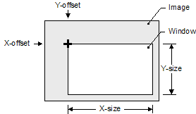
DBIW
The raster window of data to read from the input channels. The window is determined by the x-offset, y-offset, x-size, and y-size.
X-offset and y-offset define the pixel coordinate at the upper-left corner of the window. X-size is the number of pixels that define the width of the window. Y-size is the number of lines that define the height of the window.
If you do not specify a valued for this parameter, ORTHO processes the entire image.
SRCBGD
The pixels in the source image to consider as background (NoData) pixels. Typically, ORTHO processes NoData pixels in a specific manner.
-
FILE: Reads the NoData value from the metadata of the input file. If the file-level NO_DATA_VALUE metadata tag is found in the source raster, its value is used as the default for all channels in the file. ORTHO then searches for channel-level NoData tags. If a channel-level NoData tag is found, it overrides the file-level value for that channel.
If there are channel-level NoData tags, but no file-level tag, a pixel is processed as NoData when each of the channels with a NoData tag corresponds to its NoData value. In this case, channels without a NoData tag are ignored when identifying background pixels.
If NoData tags are not found in the file, a default of ALL,0 is used. To use a rule other than the default when NoData tags are not found, include it after a comma. For example, to use the NoData tags of the file, if found, enter "FILE,ANY,3"; otherwise, the rule used for the source background is "ANY,3".
FILE is the default value for this parameter.
- NONE: Considers as valid all pixels in the source image.
- ALL [, <value>]: If all channels match the values entered, the pixel is considered NoData.
- ANY [, <value>]: If any channel matches the value entered, the pixel is considered NoData.
- <values>: Processes a comma-delimited list of pixel values you specify by using the same rule as ALL [, <values>].
With ALL and ANY, the background pixel is described by the "background rule" and a list of one or more pixel values for the different image channels. The "background rule" must be entered as ALL or ANY. ALL indicates that the pixel value in each channel must match the background value entered to consider the pixel as background. ANY indicates that if any channel equals the background value, consider the pixel as background.
You can enter the background value as either a single number (applied to all channels) or as a pixel "stack". If you enter a pixel stack, but the number of values does not equal the number of channels, the list will be truncated, or the last value will be repeated, as necessary. The background values you enter are truncated to the range allowed by the data type of the source image.
- ALL,0: A pixel is considered background when all three channels are zero.
- ANY,0: A pixel is considered background when any of the three channels are zero.
- ALL,128,0,0: A pixel is considered background if its value is exactly 128 for the first channel and zero for the second and third channels.
- ALL,128,0,0,245: A pixel is considered background if its value is exactly 128 for the first channel and zero for the second and third channels. The value 245 is ignored.
- ANY,128,0: A pixel is considered background if the value in channel 1 is 128\u00e2\u20ac\u201dor\u00e2\u20ac\u201dif the value in channel 2 or 3 is zero.
- ANY,1032,0: A pixel is considered background if the value in channel 1 is 255\u00e2\u20ac\u201dor\u00e2\u20ac\u201dif the value in channel 2 or 3 is zero. The first value is truncated to the range allowed for 8U data.
FILO
- When you enter a single file name as the value of MFILE, the name of the output file will be the one you specify.
- When you enter multiple files, a folder is created by using the name you specify, and the output files are written to it. Each output file will have the same name as its corresponding input file, and be prefixed with the letter "o"; for example, o<file_name>.pix.
FTYPE
The format of the output file. The format must be of a GDB-supported type.
- PIX: PCIDSK
- TIF: Tagged Image File Format
The default is PCIDSK (.pix).
FOPTIONS
The options specific to the format to apply when creating the output file. With each, the default of no options is allowed (empty string).
Typically, the available options for a format include a compression scheme, format subtype, or other information.
OUTBGD
The background (NoData) value to use for orthorectified pixels that are not populated. Each channel is set to the same background value. The value will be truncated to the range allowed by the data type of the source image.
ULX
The upper-left-ground x-coordinate, in map units, for the output orthorectified image based on the value of MAPUNITS.
If you do not specify a value for this parameter, ORTHO calculates and uses the coordinate of the upper-left corner for the maximum extent of the orthorectified image.
When you specify a text file for MFILE, and the file contains an upper-left-corner x-coordinate, it will override the value of this parameter.
ULY
The upper-left-ground y-coordinate, in map units, for the output orthorectified image based on the value of MAPUNITS.
If you do not specify a value for this parameter, ORTHO calculates and uses the coordinate of the upper-left corner for the maximum extent of the orthorectified image.
When you specify a text file for MFILE, and the file contains an upper-left-corner y-coordinate, it will override the value of this parameter.
LRX
The lower-right-ground x-coordinate, in map units, for the output orthorectified image based on the value of MAPUNITS.
If you do not specify a value for this parameter, ORTHO calculates and uses the coordinate of the lower-right corner for the maximum extent of the orthorectified image.
When you specify a text file for MFILE, and the file contains an upper-left-corner x-coordinate, it will override the value of this parameter.
Typically, the lower-right-corner coordinate of the orthorectified image will not have this exact value, because it must conform to the upper-left coordinate and pixel size; however, the generated image will be large enough so that the lower-right x-coordinate is within the raster extents.
LRY
The lower-right-ground y-coordinate, in map units, for the output orthorectified image based on the value of MAPUNITS.
If you do not specify a value for this parameter, ORTHO calculates and uses the coordinate of the lower-right corner for the maximum extent of the orthorectified image.
When you specify a text file for MFILE, and the file contains an upper-left-corner x-coordinate, it will override the value of this parameter.
Typically, the lower-right-corner coordinate of the orthorectified image will not have this exact value, because it must conform to the upper-left coordinate and pixel size; however, the generated image will be large enough so that the lower-right y-coordinate is within the raster extents.
EDGECLIP
The percentage of the image to clip from the edges during orthorectification. Clipping applies to each edge of the image.
For example, to clip five percent from the leftmost edge and 5 percent from the right, enter 5.
The edge clipping value can either be positve (clipping from raw image) or negative (clipping from orthorectified image). The maximum and minimum values are +/-49.
If the value is negative, edge clipping occurs after the extents of the orthorectified image (ULX, ULY, LRX, LRY) are determined, but before applying tile-positioning transformation.
TIPOSTRN
An adjustment of the upper-left-corner coordinate for the orthorectified image.
By specifying an adjustment you can generate orthorectified images that fall on a specific raster grid. You do so by providing a keyword and either two or four values.
- CORNER: indicates that the values are relative to the upper-left corner of the first pixel in the output file.
- CENTER: indicates that the values are relative to the center of the first pixel in the output file.
- Stride_X
- Stride_Y
- Ref_X
- Ref_Y
The values define the position of the corner or center in relation to the raster grid.
Of the four values, only Stride_X is required. If not specified, Stride_Y defaults to the value of Stride_X, and Ref_X, Ref_Y default to zero.
- "CORNER, 20, 20, 432345.000, 5438882.000"
Depending on the distance of the tile from that point, its upper-left x-coordinate can be 432345.000, 432365.000, or any other multiple, but never 432346.000 or 432355.000.
If you specify values for this parameter, the effect applies in all scenarios, regardless of whether the image-corner coordinates come from the input file, upper-left x or y coordinate, or as a result of automatic computation.
This parameter is optional.
MAPUNITS
The projection string for the output orthorectified image. If you do not specify a projection, the map units are determined automatically.
- UTM: Universal Transverse Mercator
- SPCS: State Plane Coordinate System
- LONG/LAT: Longitude and latitude
- METER: Image along-row and along-column meters
- FEET: Image along-row and along-column feet
When you specify METER or FEET, the math model and digital elevation model (DEM) also must be METER or FEET.
When you specify a regular, Earth-referenced projection, the math model and DEM also must use a regular projection (not necessarily the same one); that is, METER and FEET are not allowed.
- Dearth
- RefLong
- RefLat
- StdParallel1
- StdParallel2
- FalseEasting
- FalseNorthing
- Scale
- Height
- Long1
- Lat1
- Long2
- Lat2
- Azimuth
- LandsatNum
- LandsatPath
- UnitsCode
LCC D350 | 0 0 3.0 46.5 44.0 49.0 700000 6600000 0 0 0 0 0 0 0 0 0 -1
You can specify the UTM grid-zone number and row, and the Earth model, as follows:
UTM [mm] [r] [Ennn]
Where:
- [mm] is the two-digit zone number between one and 60.
- [r] is the zone row: a single letter between N and X for north of the equator and between C and M for south of the equator. Zone rows A, B, Y, and Z are not supported; rows I and O do not exist.
- [Ennn] specifies the Earth model, where the model number is between zero and 19. If the Earth model is not specified, it is assumed to be E000 (Clarke 1866).
You can specify the Earth model for LONG/LAT (and other units except METER or FEET), as follows:
LONG/LAT [Ennn]
You can specify the SPCS-zone number and Earth model, as follows:
SPCS [mmmm] [Ennn]
- [mmmm] is the four-digit zone number.
If the Earth model is not specified, it is assumed to be E000 (Clarke 1866).
If you do not specify a value for MAPUNITS, the logic for determining a default ortho-coordinate system is as follows:
- If the source raster has a projected coordinate reference system (CRS)\u00e2\u20ac\u201dneither PIXEL, METER, FEET, nor LONG/LAT\u00e2\u20ac\u201dit will be used for the output orthorectified image.
- Otherwise, the CRS from the math model you specified as input is analyzed. If the math model is METER or FEET, a two-dimensional coordinate system of type METER or FEET will be selected to match.
- If the math model is based on a:
- Projected coordinate system, the same projected coordinate system is chosen.
- Geographic longitude/latitude coordinate system, a default projection based on the WGS84 datum will be selected, depending on the image position. If the image falls between 84 degrees north and 80 degrees south, a UTM projection with the appropriate zone number will be used. If the image falls in the polar regions, a universal polar stereographic (UPS) projection will be used.
BXPXSZ
The size of the horizontal pixel of the output image.
The output pixel size is expressed in the same units as the coordinate system of the orthorectified image.
If you do not specify a value for this parameter, a default pixel size is computed automatically.
This parameter is optional.
BYPXSZ
The size of the vertical pixel of the output image.
The output pixel size is expressed in the same units as the coordinate system of the orthorectified image.
If you do not specify a value for this parameter, the specified horizontal pixel size is used. If you specify neither a horizontal nor a vertical pixel size, the pixel size is computed automatically.
This parameter is optional.
FILEDEM
The name of a file, folder, or DEM index file containing DEM tiles.
The following table describes the processing of FILEDEM based on the value you specify.
| Value | Processing |
|---|---|
| Name of a single, raster-DEM file | The values of DBEC, BACKELEV, ELEVREF, ELEVUNIT and ELFACTOR are used, if specified. |
| Name of an existing folder | ORTHO reads the folder for a index.txt file. The file must be in the DEM-index format, as described in DEM index file. |
| Name of a text file | The file must have a .txt file name extension and be in the DEM-index format, as described in DEM index file. |
If you do not specify a value, the offset component of ELFACTOR and ELEVREF are used to define the height surface for orthorectification.
This parameter is optional.
DBEC
The channel number of the input digital elevation model (DEM) elevation channel to process.
This parameter is ignored if the value of FILEDEM is an empty string or a DEM-index text file.
If the value of FILEDEM is a single file, and you do not specify a value for DBEC, a channel is selected as the most likely DEM channel by using the following logic:
- If there is only one channel, it is used as the DEM channel.
- If there are two or more channels, the correct one is selected according to the following criteria, in order of precedence:
- The first channel with any one of the DEM-related metadata tags: "ELEVATION_DATUM", "ELEVATION_UNITS", "ELEVATION_FACTOR", "ELEVATION_OFFSET", "ELEVATION_SCALE", "DEM_Z_ACCURACY", "ElevationModel".
- The first channel with a description containing any of the strings: "DEM", "DSM", "DTM", "ELEVATION".
- The first 32-bit-real (32R) channel.
- The first 16-bit-integer (16U or 16S) channel.
- If no channels match the preceding criteria, the first channel in the file is selected.
BACKELEV
The background elevation (NoData) value in the input elevation channel.
If you do not specify a value for this parameter, ORTHO searches for ELEVATION_BACKGROUND or NO_DATA_VALUE metadata tags, first at the channel level, then at the file level. If this value is neither specified nor found in the metadata, a default value of -32768 is applied.
If the value of FILEDEM is an empty string or a DEM-index text file, this parameter is ignored.
This parameter is optional.
ELEVREF
The vertical reference for the elevation values in the source DEM, or for the constant value of ELFACTOR, if defined.
- MSL: Elevations are referenced to mean sea level (MSL). If you do not specify a value for this parameter, MSL is used by default. The EGM2008 geoid model will be used to convert these to ellipsoidal heights.
- ELLIPS: Elevations are referenced to the ellipsoid. The coordinate system of the DEM-raster file is read to determine which ellipsoid and datum to use; for example, if the DEM file is referenced to NAD83, the heights are assumed to be NAD83 ellipsoidal heights. If the DEM and math model are based on different coordinate systems, the heights will be converted automatically to the coordinate system of the math-model prior to processing.
If the value of FILEDEM is an empty string or a DEM-index text file, this parameter is ignored.
If you do not specify a value for this parameter, the value of the ELEVATION_DATUM metadata tag is used. If the tag does not exist in the DEM, the default value is used.
This parameter is optional.
ELEVUNIT
The units of the elevation values that are stored as pixel values in the input DEM, as specified either by the value of InputDEM: Input elevation channel or by the first value specified for Elevation scale and offset.
The units of the elevation values that are stored as pixel values in the input DEM, as specified either by the value of FILEDEM or by the first value specified for ELFACTOR.
- METER (default value)
- FEET
- US_FEET
If you specify the elevation values as FEET, the conversion factor to meters is 0.3048 (corresponding to International Feet); if you specify US_FEET, the conversion factor is 1200/3937 (corresponding to U.S. Survey Feet).
If the value of FILEDEM is an empty string or a DEM-index text file, this parameter is ignored.
If you do not specify a value for this parameter, the value of the ELEVATION_UNITS metadata tag is used. If the tag does not exist in the DEM, the default value is used.
ELFACTOR
The values or values by which to shift and scale the DEM pixel values according to the unit of measure specified for ELEVUNIT.
You can enter enter up to two values to specify this parameter: the first defines the offset while the second, optionally, defines the scale.
The conversion formula is as follows:
elevation_value = scale \u00c3\u2014 (DEM_pixel_value + offset)
If you do not specify a value for FILEDEM, only the offset value of ELFACTOR is significant. That is, the value is interpreted as a uniform elevation value in the units specified by ELEVUNIT and by using the vertical reference specified by ELEVREF.
If the value of FILEDEM is an empty string or a DEM-index text file, this parameter is ignored.
If you do not specify a value for this parameter, a default of 0.0 and and 1.0 is applied for offset and scale, respectively.
If you do not specify a value for this parameter, the values of the ELEVATION_OFFSET and ELEVATION_SCALE metadata tags are used. If the tag does not exist in the DEM, the default value is used.
PROC
The amount of memory (in megabytes) for the algorithm to use.
If you do not specify a limit for the host memory, a default of 1 GB or half the available physical memory, whichever is smaller, is applied.
SAMPLING
The pixel spacing at which rigorous calculations are performed; that is, the spacing at which the math model is evaluated to determine the location of the orthorectified pixel in the source raster. A value of 1 causes the rigorous calculation to be performed for each output pixel.
With intermediate pixels, the projection from the image to the Earth surface is approximated by linearly interpolating it from the nearest locations at which the full orthorectification operation was performed.
Entering a value of 1 will provide satisfactory results in most cases. However, with math models that are more computationally intensive, a greater value may improve performance, but at the expense of accuracy. The degree of loss in accuracy will depend on viewing geometry, and the resolution and roughness of the DEM.
RESAMPLE
The resampling method to use for orthorectification.
- NEAR: Nearest neighbor.
- BILIN: Bilinear interpolation.
- CUBIC: Cubic convolution (default).
-
SINC8,SHAPINGWINDOW=[sw],BETA=[beta]: Eight-point sin(x)/x.
Where:- SHAPINGWINDOW is a window that attenuates the SINC coefficients to reduce resampling artifacts. The value can be KAISER, HAMMING, HANN, LANCZOS, PARABOLA, or NONE. SHAPINGWINDOW is optional. The default value is KAISER.
- BETA is applicable only when the SHAPINGWINDOW is KAISER. It determines the shape of the Kaiser window; a greater value for BETA provides greater attenuation of the sinc coefficients. Its value can be between 1.0 and 10.0. BETA is optional.
-
SINC16,SHAPINGWINDOW=[sw],BETA=[beta]: 16-point sin(x)/x
Where:- SHAPINGWINDOW is a window that attenuates the sinc coefficients to reduce resampling artifacts. The value can be KAISER, HAMMING, HANN, LANCZOS, PARABOLA, or NONE. SHAPINGWINDOW is optional; the default value is KAISER.
- BETA is applicable only when the SHAPINGWINDOW is KAISER. It determines the shape of the Kaiser window; a greater value for BETA provides greater attenuation of the sinc coefficients. Its value can be between 1.0 and 10.0. BETA is optional.
-
CPLXSAR,NUMCOLS=[nc],NUMROWS=[nr],FC=[fc]: Complex SAR resampler for use only with complex data.
where:- NUMCOLS is the width of the resampling window. The value must be an odd number ranging from 1 through 33.
- NUMROWS is the height of the resampling window. The value must be an odd number ranging from 1 through 33.
- FC is the normalized central frequency of the SAR image. The value must be a number ranging from -0.5 through 0.5. If you do not specify a value, a default of 0.0 is applied. FC is optional.
- AVERAGE,NUMCOLS=[nc],NUMROWS=[nr]: An average resampler for generating downsampled products. NUMCOLS and NUMROWS can be any odd number ranging from 1 through 33. The default value is 3,3.
- MEDIAN,NUMCOLS=[nc],NUMROWS=[nr]: A median resampler for generating downsampled products. NUMCOLS and NUMROWS can be any odd number ranging from 1 through 33. The default value is 3,3.
- LAGRANGE4: Four-point Lagrange interpolation.
- LAGRANGE8: Eight-point Lagrange interpolation.
-
GAUSSIAN,DSFACTORCOL=[dc],DSFACTORROW=[dr]: Gaussian resampler.
where:- DSFACTORCOL is the fraction downsampling factor in col (>=1). If you do not specify a value, a default factor is computed automatically based on the output and input pixel sizes.
- DSFACTORROW is the fraction downsampling factor in row (>=1). If you do not specify a value, the value of DSFACTORCOL is applied, by default.
With each resampling method, the parameters MIN=[min], MAX=[max], and FILL=[NN or BGD] can be appended as a comma-delimited list. MIN and MAX define the clamp range for output pixels. This is useful when you want to keep pixel values within a certain range; for example, 1 to 2,047 if 11-bit data is stored in a 16-bit file. FILL defines the behavior when the resampling window contains NoData pixels: NN performs resampling by using the nearest-neighbor method, while BGD indicates that the output pixel will be set to the background value. By default, NN is used for FILL.
For more information about the available resampling methods, see Resampling.