Parameter descriptions
New Scene Folder
The path and name of the folder containing new image scenes to add to the mosaic. The input imagery must conform to the preprocessing requirements.
Existing Mosaic Folder
The path and name of the folder containing the existing mosaic tiles to modify.
Output Mosaic Project
The name of the mosaic project file (.mos) to create.
An accompanying folder, with the same base name, is also created. The folder contains auxiliary information that makes up the mosaic project created by the mosaic-preparation process. Unique image IDs are created automatically based on the names of the source files and listed in the project file.
If you have an existing file of the same name, and you want to overwrite it, make sure the Overwrite Results check box is selected. All existing output folders and files will be overwritten.
You can open the output mosaic project in CATALYST Professional Mosaic Tool to enhance the mosaic and perform quality-control procedures.
New Scene Order
Select the order in which to add new image scenes to the mosaic.
- Top: Place new imagery on top of the existing mosaic. Select this option to update a mosaic using new imagery.
- Bottom: Place new imagery on the bottom of the existing mosaic. Select this option to cover a "hole" in your mosaic.
NoData Value
The background value of the input images.
A pixel you designate as NoData is excluded from normalization, color balancing, and cutline generation. Images often have NoData defined in their metadata so this parameter can be defaulted.
When you specify a text file as input, you can specify the NoData value of an image in the file. The NoData value specified in the input text file takes precedence over all other sources. When a value is not specified in the text file, precedence is applied to the NO_DATA_VALUE metadata tag of the input image. If NO_DATA_VALUE metadata exists for an input channel, its value is used; otherwise, the NO_DATA_VALUE at the file level is used. Finally, if a NoData value is available in neither the text file nor the metadata, you can specify the value for this parameter.
- Text file
- Channel metadata
- File metadata
- NoData parameter value
If necessary, you can enter more than one NoData value for your input images. For example, to specify that channel 1 has a NoData value of -9999, channel 2 is 0, and channel 3 is 255, enter -9999,0,255.
Overwrite Results
Select this check box to overwrite the existing output files, if any exist. If this check box is left clear, and an output file exists in the relevant folder, the status of the job displays a message informing you of the existence and name of the output file. The message is also written to the event log of the job.
Normalization Method
The normalization to apply to each source image before color balancing, cutline generation, or mosaicking.
- Hot Spot: Removes any hot spots from the input images. A hot spot is a common distortion in aerial photographs and optical satellite images. This distortion is typically the result of solar reflections that appear circular in photographs, and tends to appear as a striped pattern in optical satellite images.
When Hot Spot is selected as the normalization method, hot spots are removed from the images by normalizing the brightness over the image by fitting a Gaussian surface to the brightness values. It does not remove the smaller spot reflections from lakes, cars, or buildings.
- Adaptive: Balances the brightness and contrast using a moving window. The adaptive filter is recommended for images with a large, irregular bright and dark pattern that cannot be modeled to a Gaussian surface. Patterns that model to a Gaussian surface are better handled by Hot Spot.
The adaptive filter adjusts the brightness and contrast over local areas, thereby improving image detail, while reducing the bright-and-dark pattern over the entire image. It applies an adaptive enhancement using a moving window to calculate the adjustment for each pixel value. The filter calculates the mean and standard deviation of the gray levels within the window and adjusts the values to match the overall mean and standard deviation of the image. The mean is used to adjust the brightness and the standard deviation is used to adjust the contrast.
Note: Because of the intensive background processing required, Adaptive normalization can be slow to produce results. - None: Applies no normalization to the input images.
Normalization Method Extra Options
When you select Adaptive for Normalization Method, you can define additional options for normalization.
To define the filter size for the adaptive normalization, enter the image_percent value to use
The default is 20 (20 percent).
Color Balancing Reference Image
The path and file name of the low-resolution mosaic image file to use for color balancing. This file is located typically in the mosaic-preparation folder related to the initial mosaic generated, and the mosaic that is being updated.
Local Color Balance Mask Layer
The layer in the input scene to use as the local color-balancing mask to exclude specified pixels from any color-balancing calculations.
Exclusion masks are useful where the same features appear radically different from one image to the other. When an exclusion mask is used for color balancing, image pixels within the masked regions are excluded from color-balancing calculations. A local exclusion mask applies only to the image that contains the mask layer.
- Last Vector: Sets the last-created vector segment in the source image as the local color-balance mask layer. The vector segment must contain a polygon, and all image pixels enclosed within it is excluded from the color-balancing calculation. When this option is selected, but no vector segment exists, all pixels are considered valid candidates for color balancing.
- Last Bitmap: Sets the last-created bitmap segment in the source image as the local color-balance mask layer. All image pixels covered by the bitmap is excluded from the color-balancing calculation. When this option is selected, but no bitmap segment exists, all pixels are considered valid candidates for color balancing.
- Specific Segment: Defines a specific segment in the source images as the local color-balance mask layer. All image pixels covered by the mask area is excluded from the color-balancing calculation. When this option is selected, a value must be specified for Local Color Balance Mask Segment.
- None: All pixels are considered valid candidates for color balancing.
Local Color Balance Mask Segment
When Specific Segment is specified for Local Color Balance Mask, this parameter specifies the number of the segment that contains polygons or bitmaps to be used to mask pixels to exclude from the color-balancing computations.
Global Color Balance Mask File
The file used to define a global color-balance mask, which identifies regions in the source images to omit from any color-balancing computation.
A global mask is useful when imagery contains, for example, massive water bodies. The global color-balance mask applies to all images in the mosaic project.
If you specify a value for this parameter, you must specify a value for Global Color Balance Mask Layer.
Global Color Balance Mask Layer
The layer in file specified for Global Color Balance Mask File that contains a global color-balance mask identifying regions in the source images to omit from any color-balancing computation.
- Last Vector: Sets the last-created vector segment in file specified for Global Color Balance Mask File as the global color-balance mask layer. The vector segment must contain a polygon, and all image pixels enclosed within it is excluded from the color balancing calculation.
- Last Bitmap: Sets the last-created bitmap segment in the file specified for Global Color Balance Mask File as the global color-balance mask layer. All image pixels covered by the bitmap is excluded from the color-balancing calculation.
- Specific Segment: Defines a specific segment in the file specified for Global Color Balance Mask File as the global color-balance mask layer. All image pixels covered by the mask area is excluded from the color-balancing calculation. When this option is selected, you must specify a value for Global Color Balance Mask Segment.
Global Color Balance Mask Segment
When Specific Segment is selected for Global Color Balance Mask Layer, this parameter specifies the number of the segment that contains polygons or bitmaps to use to mask pixels during color-balancing calculations.
Cutline Method
The cutline method used to generate polygons that enclose all the data from an image to be included in the output mosaic.
- Minimum Squared Difference: Specifies the minimum-squared-difference method. This method is suitable for most mosaicking projects, and in most cases produces the cleanest cutlines. The algorithm determines a cutline in each overlapped area between two adjacent images, with minimum-squared differences of gray values at the same locations of the region in all image channels.
- Minimum Difference: Specifies the minimum-difference method. This method is suitable for most mosaicking projects. The algorithm determines a cutline in each overlapped area between two adjacent images, with minimum differences of gray values at the same locations of the region
- Minimum Relative Difference: Specifies the minimum-relative-difference method. This method is similar to Minimum Difference, but provides better output in cases where similar sections of data appear dissimilar in different images
- Edge: Specifies the edge-feature method. This method provides better output in urban-area mosaicking or in images containing many linear features. The objective of the Edge method is to avoid placing cutlines across linear features.
- Maximum Data: Specifies that cutlines is on the boundary of the real image pixels, meaning that NoData pixels is ignored when the image boundary is determined.
- Import: Uses the specified polygons as cutlines exactly as they appear in the vector file.
- File Extents: Specifies that the cutline is the extents of the input images and does not exclude NoData pixels from the cutline generation process.
Cutline Method Extra Options
Additional options for Cutline Method.
You can specify options related to constraining polygons, which define regions where cutlines are allowed for each image, so that the generated cutlines do not cross the specified boundaries.
Values you specify for this parameter take precedence over Auto Constrain and Factor.
[<vector_file>], [<field_name>], [<segment_number>]
- vector_file is the name of an existing vector layer to use as a constraint polygon. Using a constraining vector layer is useful when at least some of the input images include features, such as clouds, that you want to exclude from the final mosaic.
- field_name is the attribute field that contains the image source.
- segment_number is the number of the vector segment that contains the constraint polygon.
- the value of its file level metadata tag: SourceID, or if that tag does not exist, then
- the base name, without the extension, of the input source image's file name.
If the field_name is not specified, MOSPREP searches the vector-segment attributes for a field named ImageSource. If the specified field name or ImageSource does not exist, an error occurs.
If the segment number is not specified, the algorithm uses the last segment from the vector file you specified. If the constraining polygon is larger than the image being processed, cutline generation is not constrained.
Auto Constrain
Select whether and how to automatically generate and apply constraint polygons when creating cutlines. Constraint polygons define regions where cutlines are allowed for each image, so that the generated cutlines do not cross the specified boundaries. You can opt to have them generated automatically based on the layout and arrangement of the images being mosaicked.
- Automatic: Determine whether constraints are required and, if so, applies one for each input image.
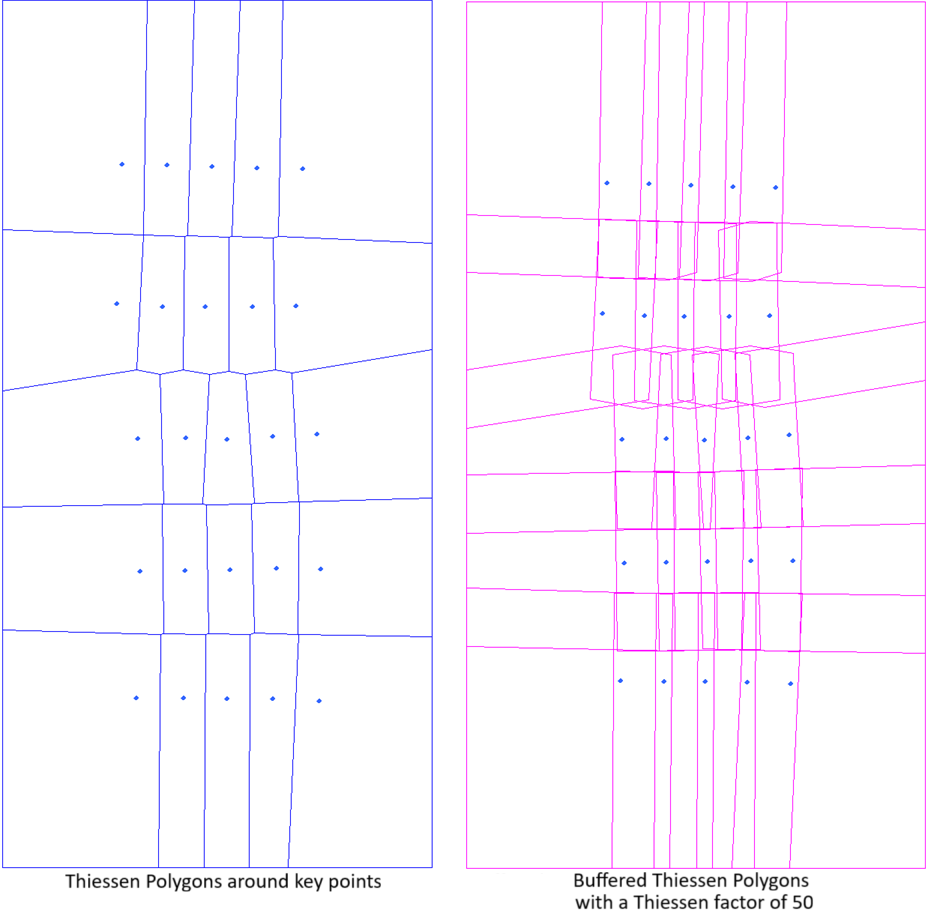
- Classic: Creates constraining polygons for the input images using PCI traditional algorithm that was developed for aerial images, that are approximately square and contain a lot of overlap. You can adjust the option by specifying a value for the Factor. In this case Factor represents the Theissen Factor. If you do not specify a value, the default value of 50 is applied.
- Strips: Create one constraint polygon for each input image using PCI algorithm that was developed for projects that have a clear pattern of strips, such as often seen with ADS data. Images must be of similar size and align in at least one direction from, for instance, aerial flight lines or satellite swaths. Cutline-constraining polygons is generated for each image based on where it and its neighbors have actual data. This method first tries to group the images in rows or columns, and chooses the strips with the most consistent distance between images. It then removes the overlap between images in each strip using, at most, two neighboring images. Finally overlap is remove between the different strips leaving a constraining polygon. The extents of the polygons can be manipulated by specifying a value for the overlap Factor. If you do not specify a value, the default value of 20 is applied.
- No: Does not apply constraint polygons.
You can adjust the effect of Auto Constrain by specifying an appropriate percentage value for Factor.
When a constraining layer is specified for Cutline Method Extra Options, do not use Auto Constrain; that is, select No.
Factor
The Factor is a percentage by which to adjust the effect of the Auto Constrain option.
This is a value between 1 and 100, with larger values causing more overlap between the generated constraint polygons; that is, the cutlines is less constrained.
Simplify Cutlines
Selected by default, this check box causes the module to simplify the cutlines for the mosaic. Simplification is to remove unsuitable vertices from the cutline shapes computed initially.
You can use this parameter in conjunction with Simplification Level to set the degree of simplification you want.
Simplification Level
Available when the Simplify Cutlines check box is selected, you can set the level of simplification you want to use.
When the Simpify Cutlines check box is clear, no simplification level is applied. When the check box is selected, a default value of 1.75 for Simplification Level is applied; otherwise, the value you specify is applied.
To create cutlines from all of the vertices computed initially, enter a value of 0. A number greater than zero increases the amount of vector reduction; the cutlines will have fewer vertices. Generally, a value of n results in 1/n of the vertices being computed. For example, a value of 2 results in approximately one half of the vertices.
Local Cutline Avoidance Mask Layer
The layer in the input scene to use as the local cutline-avoidance mask.
A local cutline-avoidance mask is used to restrict specific areas from cutline calculations; for example, to avoid cutlines crossing through clouds. When used, the image pixels in the masked regions are excluded from the cutline calculations wherever possible; if no area is more suitable in which to place a cutline, the cutline passes through the masked region. A local cutline-avoidance mask applies only to the image that contains the mask layer.
- Last Vector: Sets the last-created vector segment in the source image as the cutline-avoidance mask layer. When this option is selected, but no vector segment exists, all pixels are considered valid candidates through which a cutline can pass.
- Last Bitmap: Sets the last-created bitmap segment in the source image as the cutline-avoidance mask layer. When this option is selected, but no bitmap segment exists, all pixels are considered valid candidates through which a cutline can pass.
- Specific Segment: Defines a specific segment in the source image as the cutline-avoidance mask layer. When this option is selected, a value must be specified for Local Cutline Avoidance Mask Segment.
- None: All pixels are valid candidates through which a cutline can pass
Local Cutline Avoidance Mask Segment
When Specific Segment is selected for Local Cutline Avoidance Mask Layer, this parameter specifies the number of the segment that contains polygons or bitmaps to use to mask pixels to avoid when calculating cutlines.
Global Cutline Avoidance Mask File
The file that, in conjunction with Global Cutline Avoidance Mask Layer and Global Cutline Avoidance Mask Segment, can be used to identify common regions in all source images to omit from cutline calculations. When a global cutline-avoidance mask is used, the image pixels in the masked regions are excluded from the cutline calculations wherever possible; if there is no better area in which to place a cutline, the cutline passes through the masked region.
When you specify a value for this parameter, you must also specify a value for Global Cutline Avoidance Mask Layer.
Global Cutline Avoidance Mask Layer
The layer in the file specified for Global Cutline Avoidance Mask File to use as the global cutline-avoidance mask. When no value is specified for Global Cutline Avoidance Mask File, this parameter is ignored.
Global cutline-avoidance masks are used to restrict specific areas from cutline calculations; for example, to avoid cutlines crossing through buildings. When a global cutline-avoidance mask is used, the image pixels in the masked regions are excluded from the cutline calculations wherever possible; if there is no better area in which to place a cutline, the cutline passes through the masked region. A global cutline-avoidance mask applies to all source images that intersect the global mask layer.
- Last Vector: Sets the last-created vector segment in the file specified for Global Cutline Avoidance Mask File as the global cutline-avoidance mask layer.
- Last Bitmap: Sets the last-created bitmap segment in file specified for Global Cutline Avoidance Mask File as the global cutline-avoidance mask layer.
- Specific Segment: Defines a specific segment in the file specified for Global Cutline Avoidance Mask File as the global cutline-avoidance mask layer. When you select this option, you must specify a value for Global Cutline Avoidance Mask Segment.
Global Cutline Avoidance Mask Segment
When Specific Segment is selected for Global Cutline Avoidance Mask Layer, this parameter specifies the number of the segment that contains polygons or bitmaps to use to mask pixels to avoid when calculating cutlines.