Parameter descriptions
Input Scenes
The path and name of a folder containing a valid CATALYST Professional OrthoEngine project file (oe.prj), scenes with valid math-model segments, a text file of scenes, or one or more ADS support files (.sup).
- Path and name of a folder of input images; for example, C:\data
- Path and name of a folder containing an OrthoEngine project file; for example, C:\data\data-ingest_RAW_PAN.prj
- Path and name of a folder containing an ADS support file; for example, C:\data\<file_name>.sup
- Path and name of a folder with a wildcard to filter the imagery by file name or type; for example, C:\data\*_PAN.pix or C:\data\*_PAN.sup
- Path and name of a folder with a wildcard to filter by OrthoEngine project file; for example, C:\data\*_PAN.prj
- You can also specify an MFILE as input. An MFILE is a text file with an .mfile file name extension. For more information on this type of file, see About the MFILE format.
Output Folder
The path and name of the folder in which to write the output orthorectified image scenes.
Output images are created using a file name generated automatically that includes the image scene, state, and image type.
Output File Type
The format of the output file.
For more information on the supported file formats, see GDB-supported file formats.
Output File Options
The options to apply when creating the output file or files. The available options are specific to the file format; in each case, the default of no options is allowed.
For more information on the options available for the output file type you specify, see GDB-supported file formats.
Overwrite Results
Select this check box to overwrite the existing output files, if any exist. If this check box is left clear, and an output file exists in the relevant folder, the status of the job displays a message informing you of the existence and name of the output file. The message is also written to the event log of the job.
Send Email
If necessary, you can set up CATALYST Enterprise to send an email notification on job start and job completion.
With this check box selected, an email message is sent to each address specified in the Email Addresses box after the job starts and on completion.
You can specify one or more addresses, and each must be separated by a comma or a semi-colon. The email address of the user currently logged in displays by default.
Source Background Type
The method to use to determine which pixels in the source image to process as background (NoData) pixels. In general, if a pixel is considered NoData, the module processes it in a specific manner.
If the Any option or the All option is selected, a value must be specified for the Source Background Value parameter.
-
File Metadata, else None: reads the NoData value from the input-file metadata. The module first checks for the file-level metadata tag NO_DATA_VALUE in the source raster. If the tag is present, this value is used as a default for all channels in the file. Next, the module checks for channel-level NoData tags; if one is found, the channel-level value overrides the file-level value for that channel.
If there are channel-level NoData tags, but no file-level tag, a pixel is considered as NoData if each of the channels with a NoData tag corresponds to its NoData value. In this case, channels without a NoData tag are ignored when identifying background pixels.
If the file does not contain NoData tags, all pixels in the source image are considered valid.
- None: all pixels in the source image are to be considered valid
- All: if the pixel value in all channels matches the values provided for the Source Background Value parameter, the pixel is considered background (NoData).
- Any: if the pixel value in any channel matches the value provided for the Source Background Value parameter, the pixel is considered background (NoData).
For specific examples, see the Source Background Value parameter description.
Source Background Value
- All
- Any
The source background value is provided as either a single number (applied to all channels) or as a pixel "stack" (a comma-delimited list of values). If a pixel stack is provided, but the number of values does not equal the number of channels, the list is truncated or the last value is repeated as necessary. The background values provided is truncated to the range allowed by the source image data type.
-
Source Background Type set to All and Source Background Value set to 0: a pixel is considered background if all three channels are zero.
- Source Background Type set to Any and Source Background Value set to 0: a pixel is considered background if any of the three channels is zero
- Source Background Type set to All and Source Background Value set to 128,0,0: a pixel is considered background if its value is exactly 128 for the first channel and zero for the second and third channels
- Source Background Type set to All and Source Background Value set to 128,0,0,245: a pixel is considered background if its value is exactly 128 for the first channel and zero for the second and third channels. The value 245 is ignored.
- Source Background Type set to Any and Source Background Value set to 128,0: a pixel is considered background if the value in channel 1 is 128 OR if the value in channel 2 or 3 is zero.
- Source Background Type set to Any and Source Background Value set to 1032,0: a pixel is considered background if the value in channel 1 is 255 OR if the value in channel 2 or 3 is zero. The first value is truncated to the range allowed for 8U data.
Output Background Value
The background (NoData) value to use for pixels that are not populated.
The specified background value is truncated to the range allowed by the source image data type.
When you specify one value, all channels are set to the same NoData value. If you want to specify different values for various channels, separate the values with commas. For example, to specify -32768 for channel 1 and zero for channel 2 (and any subsequent channels), enter "-32768, 0".
Nadir
Selected by default, this check box controls whether to orthorectify ADS imagery that has a look direction of nadir.
Forward
Select this check box to orthorectify ADS imagery that has a look direction of forward.
Backward
Select this check box to orthorectify ADS imagery that has a look direction of backward.
DEM Source
The name of a single digital elevation model (DEM) file or a folder containing one or more DEM tiles.
- Name of a single DEM file; for example, C:\data\DEM\dem.pix
- Name of a folder containing one or more DEM tiles and an associated index.txt file; for example, C:\data\DEM
- Name of an index file; for example, C:\data\DEM\index.txt
The index.txt file lists the DEM files contained in the specified folder and provides information describing each DEM tile. The information in the DEM index file supersedes other DEM parameters in the module; all other DEM-related parameters are ignored. For more information about the format of the index.txt file and specific requirements for the individual DEM tiles, see Format of the DEM index file.
When the value of DEM Source is the name of an existing folder, the module searches that folder for a file named index.txt, and a set of DEM raster tiles. The index.txt file contains a single vector channel that lists the DEM files contained in the specified folder and provides information describing each DEM tile.
Output Map Units
The projection of the output imagery.
The value of this parameter must be in the PCI Projection String format.
- PIXEL: Pixel and line (not for use with DEM extraction)
-
UTM: Universal Transverse Mercator
The value specified can be the UTM grid zone number and row, and Earth model, as follows:
UTM [mm] [r] [Ennn]
where:- [mm] is the two-digit zone number between 1 and 60
- [r] is the zone row: a single letter between N and X for north of the equator and between C and M for south of the equator. Zone rows A, B, Y, and Z are not supported; rows I and O do not exist.
- [Ennn] specifies the Earth model, where the model number is between 0 and 19. If the Earth model is not specified, it is assumed to be E000 (Clarke 1866).
-
SPCS: State Plane Coordinate System
The SPCS zone number and Earth model can be specified as follows:
SPCS [mmmm] [Ennn]
where:- [mmmm] is the four-digit zone number
- [Ennn] specifies the Earth model, where the model number is between 0 and 19. If the Earth model is not specified, it is assumed to be E000 (Clarke 1866).
-
LONG/LAT: Longitude and latitude
The Earth model can be specified for LONG/LAT (and other units except PIXEL), as follows:
LONG/LAT [Ennn]
If the Earth model is not specified, it is assumed to be E000 (Clarke 1866).
-
EPSG: European Petroleum Survey Group code
You can specify the projection by entering an EPSG code defined by the Open Geospatial Consortium (OGC). For information on the code definitions, visit epsg.org and spatialreference.org.
The EPSG code is specified using the EPSG keyword followed by an integer and separated by a colon; for example:
EPSG:4326
Most common EPSG codes are supported.
-
METER: Image along-row and along-column meters
-
FEET: Image along-row and along-column feet
-
You can also specify the label of a projection you define, if the projection exists in the userproj.txt file; otherwise, you must enter the projection-parameter information as a string separated by the vertical bar (|). The projection-parameter string defines 18 parameters delimited by spaces, including the following:
- Dearth
- RefLong
- RefLat
- StdParallel1
- StdParallel2
- FalseEasting
- FalseNorthing
- Scale
- Height
- Long1
- Lat1
- Long2
- Lat2
- Azimuth
- LandsatNum
- LandsatPath
- UnitsCode
For example, the projection named 'France93' can be specified, as follows:LCC D350 | 0 0 3.0 46.5 44.0 49.0 700000 6600000 0 0 0 0 0 0 0 0 0 -1
If you do not specify a value for Output Map Units, the map unit of the input image is used for the output image. If the input data is a variety of map units, the map unit of each output image is that of its corresponding input image. In such a case, it is recommended that you specify the output map units.
You can also specify the label of a projection defined in the userproj.txt file.
Output Pixel Size
The sample size of the output imagery.
The output pixel size must be specified in the value (units) of Output Map Units; for example, when the value of Output Map Units is specified as a UTM zone, the pixel output size must be in meters. When the value is specified as Long/Lat, the pixel size must be in decimal degrees.
If a single value is specified, that value applies to both x and y values.
If no value is specified for this parameter, the pixel output size is based on the input math model associated with each scene in the input folder.
Resampling Method
The resampling method to use during processing.
- Cubic: cubic convolution. This method determines the gray level from the weighted average of the 16 pixels closest to the specified input coordinates and assigns that value to the output coordinates. The resulting image is slightly sharper than one produced by bilinear interpolation, and it does not have the disjointed appearance produced by nearest-neighbor interpolation. This is the default value.
- Nearest Neighbor: nearest-neighbor interpolation. This method identifies the gray level of the pixel closest to the specified input coordinates and assigns that value to the output coordinates. Although this method is the most efficient in computation time, it introduces small offsets in the output image. The output image may be offset spatially by up to half a pixel, which may cause the image to have a jagged appearance.
- Bilinear: bilinear interpolation. This method determines the gray level from the weighted average of the four closest pixels to the specified input coordinates and assigns that value to the output coordinates. An image with a smoother appearance than nearest-neighbor interpolation is created, but the gray-level values are altered in the process, resulting in blurring or degraded image resolution.
- Lagrange-4: four-point Lagrange interpolation
- Lagrange-8: eight-point Lagrange interpolation
- Sinc-8: eight-point sin(x)/x
- Sinc-16: 16-point sin(x)/x
- Average: Average resampler for creating downsampled products
- Gaussian: Gaussian resampler
- Median: Median resampler for creating downsampled products
Resampling Method Extra Options
- Sin(x)/x with an 8 x 8 window
- Sin(x)/x with a 16 x 16 window
SHAPINGWINDOW=[sw],BETA=[beta]
where:
SHAPINGWINDOW specifies a window to attenuate the SINC coefficients to reduce resampling artifacts. The value can be KAISER, HAMMING, HANN, LANCZOS, PARABOLA, or NONE. SHAPINGWINDOW is optional; the default value is KAISER. BETA is applicable only when SHAPINGWINDOW is KAISER. SHAPINGWINDOW determines the shape of the KAISER window; a larger BETA value produces greater attenuation of the SINC coefficients. Its value can be between 1.0 and 10.0. BETA is optional.
- Average
NUMCOLS=[nc],NUMROWS=[nr]
- Median
NUMCOLS=[nc],NUMROWS=[nr]
where:
NUMCOLS and NUMROWS can be any value between 1 and 11.
- Gaussian
DSFACTORCOL=[dc],DSFACTORROW=[dr]
where:
DSFACTORCOL is the fraction downsampling factor in col (>=1). If not specified, a default factor is computed automatically based on the output and input pixel sizes. DSFACTORROW is the fraction downsampling factor in row (>=1). If not specified, default to the value of DSFACTORCOL.
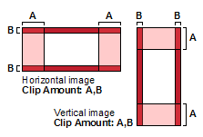
Clip Amount
The amount to clip from each edge of the input data. You can express the amount to clip as either a percentage or a number of pixels based on the value selected for the Clip Units parameter.
In aerial workflows, surveys are typically flown to ensure there is sufficient overlap between images to allow for correction, such as for building lean. This parameter clips the image to produce cleaner, more accurate orthorectified images.
In Figure 1, the first value specifies the amount to clip from the long ends of the image (A); the second value defines the amount to clip from the short ends of the image (B).
For example, with an image that is 10000 x 7000 pixels, a specified value of 20,5 (with Percent selected for the Clip Units parameter) clips 20 percent of the image from each of the long ends), and five percent from the narrow ends.
You can also specify the clip units in pixels. For example, with the same 10000 x 7000 image, a clip amount of 1500,1000 (with Pixels selected for the Clip Units parameter) produces an output image of 7000 x 5000 pixels.
If you specify a single value; for example, 15, it is interpreted as 15,15.
When you specify a value for this parameter, you must select a value for the Clip Units parameter.
Clip Units
The unit to use for the value of the Clip Amount parameter.
- Percent: defines the amount of clipping in units of percentage, based on the full size of the image
- Pixels: specifies the exact number of pixels to clip
When you specify a value for the Clip Amount parameter, this parameter is mandatory; otherwise, it is not required.
Grid Reference Point
An upper-left corner coordinate adjustment for the orthorectified image.
With this parameter, you can create ortho images that fall on a specific raster grid, ensuring that all ortho images align perfectly without the need for resampling. The grid is created according to the values specified and the output resolution of the ortho images. The ortho images created are aligned to the grid using the upper-left corner of the top-left pixel in the ortho image.
The grid reference point is specified using two values (x-reference, y-reference), which define the position of the top-left corner of the raster grid.
Sample input
"432345.000, 5438882.000"
The preceding values specify that the upper-left coordinate of the reference point is 432345.000, 5438882.000. Depending on the distance of the tile from that point, the upper-left x-coordinate of the ortho image could be 432345.000, 432365.000, or any other multiple of the resolution.
If values are specified for this parameter, it is applicable in all scenarios, whether the image-corner coordinates are determined from the input file or through automatic computation.
If no values are specified for this parameter, a default value of 0,0 (x-reference, y-reference) is applied.
Raster Channels
A comma-delimited list of channels; for example, 1,2,5.
This parameter is optional. If you do not specify a value, all of the channels in the input files is used.
Sampling Interval Range
The range from which the sampling interval is selected. The range consists of two values: a minimum and maximum sampling interval. When you specify a range, the sampling interval is calculated based on the ratio of the resolution of the digital elevation model (DEM) and that of the output orthorectification.
When you specify only a single value, the value is used as the sampling interval and not calculated.
Sampling Interval Range = 1, 4
DEM resolution     = 10m
Ortho resolution   =  5m
Ratio = 2
Sampling Interval = 2
Sampling Interval Range = 2, 6
DEM resolution     = 1m, 1m
Ortho resolution   = 0.1m, 0.2m
Ratio = 10, 5
Sampling Interval = floor((0.1+0.2) / 2) = 7.5
Final Sampling Interval = 6 (because maximum in range forces to 6)
Sampling Interval Range = 2, 4
DEM resolution     = 1m, 1m
Ortho resolution   = 5m, 5m
Ratio = 1/5, 1/5
Sampling Interval = floor((1/5+1/5) / 2) = 0
Final Sampling Interval = 4 (because minimum in range forces to 4)
The sampling interval is the pixel spacing at which the math model is evaluated to determine the source raster location of the orthorectified pixel. A value of 1 performs a rigorous calculation on each output pixel.
With sampling intervals of 2 or greater, the intermediate pixels are the projection from the image to the Earth surface and is approximated by linearly interpolating it from the nearest locations at which the full orthorectification operation was performed.
A value of 1 is suitable in most situations. With math models that are more computationally intensive, a higher value can improve performance, but is at the expense of accuracy. The amount of loss of accuracy depends on the viewing geometry, resolution of the digital elevation model (DEM), and roughness of the DEM. When the area of interest features rugged areas, a higher value may degrade the detail of the terrain correction.