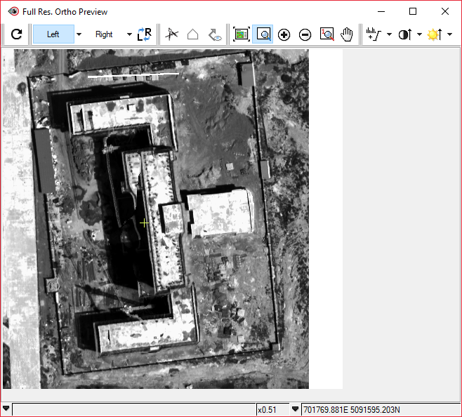
The Full Res. Ortho Preview window displays a full-resolution preview of the images orthorectified using the active digital elevation model (DEM), in which you can view changes in finer detail. When you apply changes to the DEM and regenerate the ortho images, the preview displays an accurate depiction of how those changes will affect images orthorectified using the updated DEM.
The following table describes the toolbar buttons in the Full Res. Ortho Preview window.
| Button | Label | Description |
|---|---|---|
 |
Regenerate Ortho Preview | Regenerate the full-resolution ortho preview using the most recent changes to the DEM. |
 |
Left Image | Display only the left-ortho image. Click the arrow for a menu of additional viewing options.
The left image is selected, by default. However, you can select any of the images on the Left Image or Right Image menu to select what you want to display in the Full Res. Ortho Preview window. That is, you can select any image on either menu to display (and compare when you click Flicker Left/Right Image). Note: The button label changes according to the selected option.
|
 |
Right Image | Display only the right-ortho image. Click the arrow for a menu of additional viewing options.
You can select any of the images on the Right Image or Left Image menu to select what you want to display in the Full Res. Ortho Preview window. That is, you can select any image on either menu to display (and compare when you click Flicker Left/Right Image). Note: The button label changes according to the selected option.
|
 |
Flicker Left/Right Image | Flicker the display based on what you have selected on either the Left Image or Right Image menu. Items that appear to move in the display indicate differences between the two images. With some features, such as buildings, trees, or cars, movement is expected; ideally, there should be very little movement at the ground level in the display. |
 |
Vector Editing Toolbar | Display the Focus vector-editing toolbar, which you can use to modify polygon masks.
Note: For more information, see About the Vector Editing toolbar.
|
 |
New Polygon | Put the polygon layer in edit mode, allowing you to create a new polygon mask. |
 |
View DEM Editing Polygons | Switch the visibility of existing DEM editing polygons between on and off. You can use the vector-editing tools to modify the polygons in this window. |
 |
Zoom to Overview | Adjust the magnification so that the entire image appears in the viewer. |
 |
Zoom Interactive | Drag a rectangle over the area you want to magnify. |
 |
Zoom In | Increase the magnification incrementally, centered on the cursor.
You can also:
|
 |
Zoom Out | Decrease the magnification incrementally, centered on the cursor.
You can also:
|
 |
Zoom 1:1 | Adjust the magnification so that one screen pixel displays one image pixel, centered on the cursor. |
 |
Pan | Drag the image to view a specific area.
You can also:
|
 |
Enhancements | Apply enhancements to the image in the viewer. Enhancements make the image on the screen clearer and easier to interpret without changing the actual values of the image file.
Available enhancements are:
For more information, see Enhancement options. Click the arrow for a menu of additional enhancement options. |
 |
Contrast | Adjust the difference between the light and dark extremes for all images displayed. Click the arrow for a menu of additional options. |
 |
Brightness | Adjust the overall luminosity (amount of light) for all images displayed. Click the arrow for a menu of additional options. |
 |
Status Bar | Displays system messages, zoom-image pixel, and current position of the cursor.
|
| Menu command | Description |
|---|---|
| Left Mosaic | Mosaic of all raw left images used to derive the DEM being edited that intersect the preview region that defines the extents of the Full Res. Ortho Preview window. |
| Right Mosaic | Mosaic of all raw right images used to derive the DEM being edited that intersect the preview region that defines the extents of the Full Res. Ortho Preview window. |
| Middle Mosaic* | Mosaic of all raw middle (nadir) images used to derive the DEM being edited that intersect the preview region that defines the extents of the Full Res. Ortho Preview window. |
| Stereo | RGB map layer that combines the left and right mosaics. The left mosaic displays in the red gun and the right mosaic displays in the green and blue guns. Stereo provides another way for you to assess your DEM. Areas that have an obvious color hue, such as cyan, indicate locations where the left and right images are not in perfect agreement and, therefore, where additional editing of the DEM may be required. |
| Tri-stereo* | RGB map layer that combines the left, right, and middle mosaics. The left mosaic, which corresponds to the forward-looking images, displays in the red gun. The right mosaic, which corresponds to the backward-looking images, displays in the green gun. The middle mosaic, which is the nadir imagery, displays in the blue gun. Tri-stereo provides another way for you to assess your DEM. Areas that have an obvious color hue, such as cyan, indicate locations where the forward, backward, or nadir images are not in perfect agreement and, therefore, where additional editing of the DEM may be required. |
| L Ortho 1: o<imagID>.pix | Ortho preview of the first left image. |
| R Ortho 1: o<imagID>.pix | Ortho preview of the first right image. |
| M Ortho 1: o<imagID>.pix* | Ortho preview of the first middle (nadir) image. |
| L Ortho 2: o<imagID>.pix | Ortho preview of the second left image. |
| R Ortho 2: o<imagID>.pix | Ortho preview of the second right image. |
| M Ortho 2: o<imagID>.pix* | Ortho preview of the second middle (nadir) image. |