Parameter descriptions
MFILE
The names of image files, a folder, or a text file that contains the input images to process. If necessary, you can use wildcards, such as the asterisk (*) in the value string.
- A specific file-name pattern; for example, "C:\data\*.pix"
- All of the files in a folder; for example, "C:\data"
- An existing text file that contains references to multiple files; for example,"C:\data\list.txt"
If you use a wildcard, DEMEDPREP processes all files that match the specified file-name pattern.
If you specify a folder, DEMEDPREP processes all the recognized image files in that folder.
If you specify the name of a text file, DEMEDPREP processes the images listed in the file. Each image should be listed on a separate line. Any other entries that follow the file path and name on each line are ignored.
Each image file selected for processing must have a segment with a valid math model. DEMEDPREP uses the last math-model segment in each file. If no math model is found in an image, it is excluded from further processing. If no image with a math model is found, processing stops, and an error message is displayed.
FILEDEM
The name of an existing file containing DEM data to prepare for editing. The file must be in a supported raster format.
DBEC
The elevation channel to prepare for editing.The default value is 1.
- ELEVATION_DATUM
- ELEVATION_OFFSET
- ELEVATION_SCALE
- ELEVATION_UNITS
- NO_DATA_VALUE
- ELEVATION_BACKGROUND(deprecated and superseded by theNO_DATA_VALUEtag)
If any of the tags is missing or has an invalid value, processing stops, and an error message is displayed.
FILO
The name of a PCIDSK (.pix) file to contain an editable DEM channel, and the derived cutlines of epipolar pairs or triplets. The file you specify must not exist already or have the same file name as your input DEM file.
If the file you specify does not exist, it is created during processing in the projection of your input DEM file with one elevation channel. The channel is either copied from or linked to the input elevation channel, as discussed in the parameter description when you specify whether to create a linked file.
If the file is the same name as your input DEM file, creating a linked file is not necessary (it is not processed). The data in the channel you specified as the input elevation channel will be edited in place. If the elevation channel cannot be written to, processing stops, and an error message is displayed. In either case, the cutlines are saved in the file you specify in a vector segment namedCutlines.
LINKFILE
Whether the output file specified in theFILOparameter should be created as a link file to theFILEDEM. The default value isNo.
If you selectNo, a new file is created containing the editable DEM channel with a copy of the data from the input elevation channel, and cutlines of epipolar pairs or triplets. Otherwise, the new file is created as a link to the input elevation channel specified in theDBECparameter.
If the file containing the DEM channel and cutlines cannot be written to, processing stops, and an error message is displayed.
SELMTHD
The method to use to form the epipolar pairs. The default isPair.
-
PAIR: automatically forms pairs according to the order in which the files are listed in the input folder or file. No other processing or screening of images is performed.
For example:- File1 uses the left image for pair 1
- File 2 uses the right image for pair 1
- File 3 uses the left image for pair 2
- File 4 uses the right image for pair 2
-
MAXIMUM(Maximum): for each image, a single epipolar pair is created using the image that provides the most amount of overlap. If necessary, you can use theMinimum Overlap (%)(MINPC) parameter to specify the minimum percentage of overlap required to create a pair for consideration.
-
ALL: for each image, epipolar pairs are generated using all images that overlap above the value specified for the Minimum Overlap (%)(MINPC) parameter.
-
OPT(Optimum): epipolar pairs are generated to cover the entire project area, but an attempt is made to eliminate excessive duplication. The value of the Minimum Overlap (%)(MINPC) parameter is ignored with this method. Before pairs are selected, the images are assigned to contiguous flight lines, and only pairs of images from the same flight line are considered, to eliminate side overlaps. This method is intended for processing airborne images, where the concept of flight lines is well defined.
-
DENSE: epipolar pairs are generated to cover the entire project area, with every image used exactly twice: as a left image and a right image of adjacent pairs. The value of the Minimum Overlap (%)(MINPC) parameter is ignored with this method. Before pairs are selected, the images are assigned to contiguous flight lines, and only pairs of images from the same flight line are considered, to eliminate side overlaps. This method is intended for processing airborne images, where the concept of flight lines is well defined.
-
STRIPS: TheSTRIPSselection method uses the same concept as theDENSEselection method. But it groups the images into flight lines using their geographic data extents. TheSTRIPSselection method will only give good results if the flight lines are straight and parallel to each other.
The STRIPS method allows up to two values for the MINPC parameter:- Along-Track-MINPC: this applies between images within a flight line. If ommitted the default value is: 60
- Across-Track-MINPC: this applies between images between different flight lines. If you provide only one value for MINPC, then it applies to the Along-Track-MINPC only and the Across-Track-MINPC is set to 100, effectively turning off across track pairing. This behavior is to maintain backwards compatibility with how the STRIPS method worked before the two values were introduced.
-
AUTO: TheAUTOselection method will use the best results from theSTRIPSandDENSEselection methods. It will use the selection method that generated the fewest flight lines.
-
TRI(Triple Stereo): this method is designed for triple-stereo images. It assembles them into triplets of Forward, Nadir and Backward looking images. Incomplete triplets, that is, pairs are also accepted, for example Forward and Nadir, in which case the data is treated as stereo rather than tri-stereo. The values of theMinimum Overlap (%)(MINPC) and Flight-line-break angle (deg) (BREAKANG) parameters are ignored with this method.
With the Max,All, Opt(Optimum), andDensemethods, you can specify additional options with a KEY=value. Each KEY=value pair must be preceded by a comma.
The following KEYs and their values are recognized:
-
SSL: Stereo separation lower limit, in degrees. Stereo separation is the angle between the lines of sight from the centroid of the image-overlap area to the positions of the two cameras or satellites. If SSLis specified, the pairs with stereo separation lower than the provided value are not formed. If the SSLkey is not provided or SSLorSSL= by itself is specified, the limit is set at 1(one degree). The value you specify must be greater than0degrees and less than180degrees.
-
SSU: Stereo separation upper limit, in degrees. If SSUis specified, the pairs with stereo separation higher than the value you specify are not formed. If the SSUkey is not provided orSSU or SSU= by itself is specified, the limit is set at 140degrees. The value you specify must be greater than0degrees and less than180degrees. If bothSSLand SSUare provided,SSL must be lower than SSU.
-
SAR: Specifies SAR-satellite-specific parameters to use in forming SAR epipolar pairs. You specify the parameters by using single-letter codes, and they can be provided as a contiguous string of letters that does not include the coma. The actual values are extracted from the metadata of each image. Candidate pairs are accepted if all specified SAR parameters match exactly; otherwise, the candidate pairs are rejected.
The following parameters (and the corresponding metadata tags) are recognized:- N: Satellite platform name, provided by the PlatformName tag
- L: SAR look direction, provided by the LookDirection tag
- O: SAR orbit direction, provided by the OrbitDirection tag
- B: SAR beam mode (without beam number), extracted from the BeamMode tag
- P: SAR polarizations, provided by the Polarizations tag
- T: Product type, provided by the ProductType tag
The SARkey is evaluated only for the MaxandAll selection methods. SAR images without the required metadata tags are omitted from further analysis.
If SARorSAR= by itself is specified, all of the preceding parameters must be identical for two images to form a pair (that is, the default is equivalent to SAR=NLOBPT).If you specify only a partial list, the parameters included in the list must match for the two images to form a pair, and the parameters not included in the list are ignored.Special formsSAR=ALL andSAR=NONE are also recognized.The NONE option disables all checks, but ensures that only SAR (as opposed to optical) images are used in forming pair candidates.
CAUTION:The pairs accepted according to the criteria provided in the SARkey are still screened according to their stereo-separation criteria defined by theSSL andSSUkeys. They must also satisfy the minimum-overlap percentage, as defined by the Minimum Overlap (%)(MINPC) parameter.
MINPC
The percentage of minimum overlap acceptable between two images for them to be considered a valid pair. The value you specify must be between0and100.
The default value is50(50 percent).
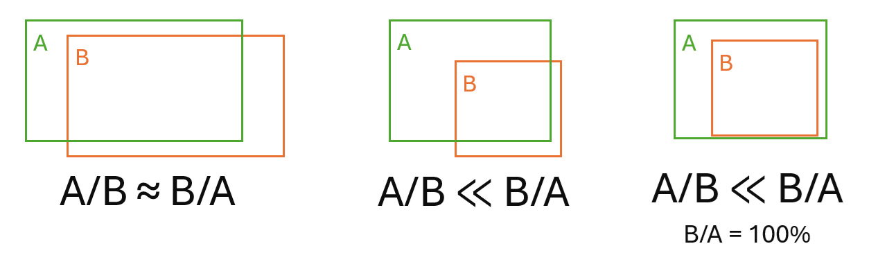
The first step in the pairing is to evaluate every pair to determine if the overlap is greater or equal to the value of this parameter. For each image pair,AandB, two overlap values are calculated:A/BandB/A.Pairs are rejected when the minimum ofA/BandB/Ais less than the valueMINPC / 100. The difference between the values A/B versus B/A is larger the more the two image sizes differ.
- A/Bis the area ofArelative to the area ofB
- B/Ais the area ofBrelative to the area ofA
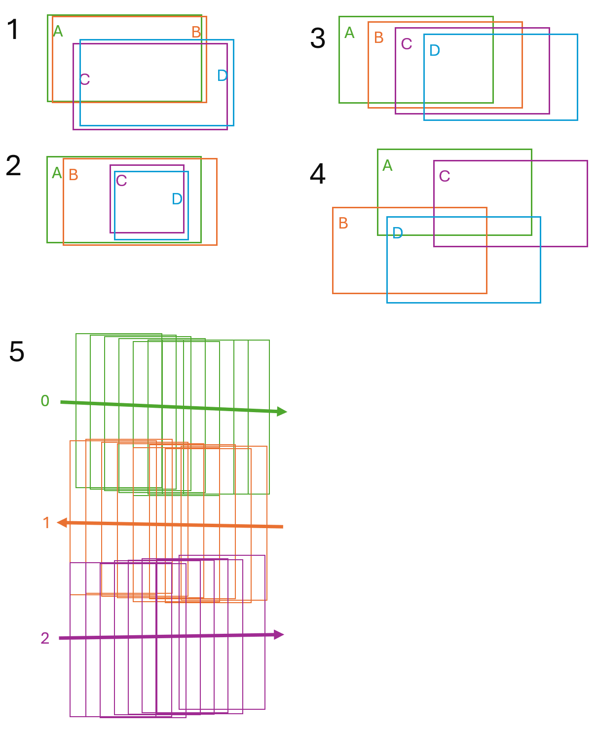
Example Overlap Scenarios:
- Stereo image sets - examples1and2: when your data consists of stereo image sets, often forward and backward looking, you want only the stereo images to be paired together.In this case setMINPCto a high value, such as75or higher.For this example, the high value accepts the pairsABandCD, and rejects the pairsAC,AD,BC, andBD.
- Non-stereo image set - example3: when your data consists of non-stereo image sets, similar to this example, you usually to pair images that are close to one another.In this case the default value value ofMINPCis often good. For this example, it produces the pairs:AB,AC,BC,BD, andCD.
- Non-stereo image set - example4: for random images you want pair images might want to be less restrictive.In this case use a low value forMINPC, such as40.For this example, it produces the pairs:AB,AC, andBD.
- Strips - example 5: when the images are organized into flight lines (strips) with differing along-track and across-track overlap. In this case use STRIPS SELMTHD wioth two MINPC values, such as 60,20.
BREAKANG
The break angle of the flight line, which is used to determine the end of a flight line. The vector angles between image centers are calculated, and if the vector angle between two image centers is greater than the break-angle threshold, this is determined to be the end of the flight line, at which point a new one begins. The default value is22.5(22.5 degrees).
This parameter is optional.