Parameter descriptions
Input Scenes
The name of the folder that contains a valid CATALYST Professional OrthoEngine project file (oe.prj), valid GDB-supported images, or a text file of images to be processed.
When only a folder name is specified, the module processes all recognized .tif and .pix image files in that folder.
- Path and name of a folder of input images; for example, C:\data
- Path and name of a folder containing an OrthoEngine project file; for example, C:\data\<file_name>.prj
- Path and name of a folder with a wildcard to filter the imagery by file name or type; for example, C:\data\*.pix
- Path and name of a folder with a wildcard to filter by OrthoEngine project file; for example, C:\data\*.prj
- You can also specify an MFILE as input. An MFILE is a text file with an .mfile file name extension. For more information on this type of file, see About the MFILE format.
Output Folder
The path and name of the folder to which to write the output files.
Output DEM Base Name
The base name of the output digital surface model (DSM) and digital terrain model (DTM) files. This name is prepended to all of the output DSM and DTM files.
If no value is specified for this parameter, the default digital elevation model (DEM) base name is dem.
Save Intermediate Files
Select this check box to save any supporting files created during processing.
By keeping the files, you can use them to analyze intermediate results and, if necessary, fix any minor issues. You can then restart the job without having to regenerate all the supporting data, thereby reducing processing time.
Overwrite Results
Select this check box to overwrite the existing output files, if any exist. If this check box is left clear, and an output file exists in the relevant folder, the status of the job displays a message informing you of the existence and name of the output file. The message is also written to the event log of the job.
Send Email
If necessary, you can set up CATALYST Enterprise to send an email notification on job start and job completion.
With this check box selected, an email message is sent to each address specified in the Email Addresses box after the job starts and on completion.
You can specify one or more addresses, and each must be separated by a comma or a semi-colon. The email address of the user currently logged in displays by default.
Output Pixel Size
The size of the output pixel in the DSM being created and, if applicable, the DTM. The size of the output pixel can be created either as a multiple of the ground sample distance (GSD) or you can specify a custom size.
- 1 x GSD: create an output pixel that is the GSD multiplied by one.
- 2 x GSD: create an output pixel that is the GSD multiplied by two.
- 3 x GSD: create an output pixel that is the GSD multiplied by three.
- 4 x GSD: create an output pixel that is the GSD multiplied by four.
- 5 x GSD: create an output pixel that is the GSD multiplied by five.
- 10 x GSD: create an output pixel that is the GSD multiplied by 10.
- Custom: specify a custom pixel size with the value of the Custom Size box and, if necessary, the unit of measurement in the Output Map Units box. That is, you need only specify the map units if you are changing the projection of the output imagery. For more information about setting up a custom output pixel size, see the description of Custom Size and Output Map Units, respectively.
Custom Size
Available when you select Custom for Output Pixel Size, the custom pixel size of the output DSM, DTM, or both.
For example, when Output Map Units is UTM, the output pixel size must be in meters. With Long/Lat, the output pixel size must be in decimal degrees.
Output Map Units
The projection of the output imagery.
The value of this parameter must be in the PCI Projection String format.
- PIXEL: Pixel and line (not for use with DEM extraction)
-
UTM: Universal Transverse Mercator
The value specified can be the UTM grid zone number and row, and Earth model, as follows:
UTM [mm] [r] [Ennn]
where:- [mm] is the two-digit zone number between 1 and 60
- [r] is the zone row: a single letter between N and X for north of the equator and between C and M for south of the equator. Zone rows A, B, Y, and Z are not supported; rows I and O do not exist.
- [Ennn] specifies the Earth model, where the model number is between 0 and 19. If the Earth model is not specified, it is assumed to be E000 (Clarke 1866).
-
SPCS: State Plane Coordinate System
The SPCS zone number and Earth model can be specified as follows:
SPCS [mmmm] [Ennn]
where:- [mmmm] is the four-digit zone number
- [Ennn] specifies the Earth model, where the model number is between 0 and 19. If the Earth model is not specified, it is assumed to be E000 (Clarke 1866).
-
LONG/LAT: Longitude and latitude
The Earth model can be specified for LONG/LAT (and other units except PIXEL), as follows:
LONG/LAT [Ennn]
If the Earth model is not specified, it is assumed to be E000 (Clarke 1866).
-
EPSG: European Petroleum Survey Group code
You can specify the projection by entering an EPSG code defined by the Open Geospatial Consortium (OGC). For information on the code definitions, visit epsg.org and spatialreference.org.
The EPSG code is specified using the EPSG keyword followed by an integer and separated by a colon; for example:
EPSG:4326
Most common EPSG codes are supported.
-
METER: Image along-row and along-column meters
-
FEET: Image along-row and along-column feet
-
You can also specify the label of a projection you define, if the projection exists in the userproj.txt file; otherwise, you must enter the projection-parameter information as a string separated by the vertical bar (|). The projection-parameter string defines 18 parameters delimited by spaces, including the following:
- Dearth
- RefLong
- RefLat
- StdParallel1
- StdParallel2
- FalseEasting
- FalseNorthing
- Scale
- Height
- Long1
- Lat1
- Long2
- Lat2
- Azimuth
- LandsatNum
- LandsatPath
- UnitsCode
For example, the projection named 'France93' can be specified, as follows:LCC D350 | 0 0 3.0 46.5 44.0 49.0 700000 6600000 0 0 0 0 0 0 0 0 0 -1
If you do not specify a value for Output Map Units, the map unit of the input image is used for the output image. If the input data is a variety of map units, the map unit of each output image is that of its corresponding input image. In such a case, it is recommended that you specify the output map units.
You can also specify the label of a projection defined in the userproj.txt file.
Elevation Reference/Datum
The vertical reference for the elevation values in the source digital elevation model (DEM), or for the constant value of the Elevation Offset and Elevation Scale parameters, when available, and specified.
Available values are as follows:
- Mean Sea Level: Elevations are referenced to mean sea level (MSL). The EGM2008 geoid model is used to convert the elevations to ellipsoidal heights.
- Ellipsoid: Elevations are referenced to the ellipsoid. The coordinate system of the DEM raster file is examined to determine which ellipsoid and datum to use. For example, if the DEM file is referenced to NAD83, the heights are assumed to be NAD83 ellipsoidal heights. If the DEM and math model are based on different coordinate systems, the heights are converted automatically to the math-model coordinate system before use.
- Automatic: Select this option when you want the module to automatically determine the elevation reference based on your input data. The DEM is above mean sea level (MSL) when the input satellite data is using a Toutin math model or when the input aerial data uses exterior orientation in MSL. With all other cases the output DEM is in ellipsoidal heights.
Failed Pixel Value
The value attributed to pixels containing distortion or incorrect elevation values.
If no value is specified, a default value of -500 is applied.
Background Elevation
The pixel value representing background elevation (pixels where no elevation value is present) in the input digital elevation model (DEM).
If no value is specified for this parameter, the module checks for ELEVATION_BACKGROUND or NO_DATA_VALUE metadata tags, first at the channel level, and then at the file level. If a value is neither specified nor found in the metadata, the default value of -32768 is used for 16S and 32R data, 65535 for 16U, and 0 for 8U.
Pair Selection Method
The method to use to form epipolar pairs.
- All: Creates pairs from all images that overlap above the specified Minimum Overlap percentage.
- Maximum: Creates pairs from images that demonstrate the highest amount of overlap. Use the parameter Minimum Overlap to specify the minimum amount of overlap.
- Pair:
For use with stereo data - creates pairs according to the order in which the files are listed in the input file or folder.
When an MFILE is specified for Input Scenes, then the files are paired by line.
Using and MFILE with the Pair gives you complete control over how images are paired, for example:
- Pair 1: line 1 / line 2
- Pair 2: line 3 / line 4
- Pair 3: line 5 / line 6
- Pair 1: file1.pix / file2.pix
- Pair 2: file3.pix / file4.pix
- Pair 3: file5.pix / file6.pix
- Pair 1 (FWD/BWD): SV1-02_20210617_L2A0001056836_8032100211190004_01-1_RAW_PAN.pix / SV1-02_20210617_L2A0001056836_8032100211190004_01-2_RAW_PAN.pix
- Pair 2 (FWD/BWD): SV1-02_20210722_L2A0001080080_8032100211190013_01-1_RAW_PAN.pix / SV1-02_20210722_L2A0001080080_8032100211190013_01-2_RAW_PAN.pix
- Pair 3 (FWD/BWD): SV1-04_20210618_L2A0001057239_8032100211190006_01-1_RAW_PAN.pix / SV1-04_20210618_L2A0001057239_8032100211190006_01-2_RAW_PAN.pix
- Pair - Contiguous:
Forms contiguous pairs according to the order in which the files are listed in Input Scenes.
When an MFILE is specified, then the files are paired by line, where each line is paired with the previous and the line entry, for example:
- Pair 1: line 1 / line 2
- Pair 2: line 2 / line 3
- Pair 3: line 3 / line 4
- Pair 1: file1.pix / file2.pix
- Pair 2: file2.pix / file3.pix
- Pair 3: file3.pix / file4.pix
- Automatic (Airphoto): Automatically chooses the best pairing between the Dense and Strips methods.
- Dense (Airphoto): Forms pairs using each image twice as a left image and a right image of adjacent pairs. Before pairs are selected, the images are assigned to contiguous flight lines. To eliminate side overlaps, only pairs of images from the same flight line are considered. The Dense method is intended for use in processing airborne images, where the concept of flightlines is well defined.
- Optimium (Airphoto): Provides full-area coverage with minimum duplication that meets the overlap and convergence criteria. The Optimium method is intended for use in processing airborne images, where the concept of flightlines is well defined.
-
Strips (Airphoto):: The Strips selection method uses the same concept as the DENSE selection method. But it groups the images into flight lines using their geographic data extents. The Strips selection method will only give good results if the flight lines are straight and parallel to each other.
The Strips method allows up to two values for the Minimum Overlap parameter:- Along-Track-MINPC: this applies to images within a flight line. If ommitted the default value is: 60
- Across-Track-MINPC: this applies to images between different flight lines. If you provide only one value for MINPC, then it applies to the Along-Track-MINPC only and the Across-Track-MINPC is set to 100, effectively turning off across track pairing. This behavior is to maintain backwards compatibility with how the Strips method worked before the two values were introduced.
Minimum Overlap
The minimum percentage (MINPC) amount of overlap acceptable between two images for them to be considered a valid pair. If no value is specified for this parameter, the minimum-overlap percentage defaults to 50 percent.
The first step in the pairing is to evaluate every pair to determine if the overlap is greater or equal to the value of this parameter. For each image pair, A and B, two overlap values are calculated: A/B and B/A. Pairs are rejected when the minimum of A/B and B/A is less than the value MINPC / 100. The difference between the values A/B versus B/A is larger the more the two image sizes differ.
- A/B is the area of A relative to the area of B
- B/A is the area of B relative to the area of A
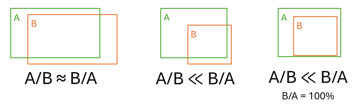
Example Overlap Scenarios:
- Stereo image sets - examples 1 and 2: when your data consists of stereo image sets, often forward and backward looking, you want only the stereo images to be paired together. In this case set MINPC to a high value, such as 75 or higher. For this example, the high value accepts the pairs AB and CD, and rejects the pairs AC, AD, BC, and BD.
- Non-stereo image set - example 3: when your data consists of non-stereo image sets, similar to this example, you usually to pair images that are close to one another. In this case the default value value of MINPC is often good. For this example, it produces the pairs: AB, AC, BC, BD, and CD.
- Non-stereo image set - example 4: for random images you want pair images might want to be less restrictive. In this case use a low value for MINPC, such as 40. For this example, it produces the pairs: AB, AC, and BD.
- Strips - example 5: when the images are organized into flight lines (strips) with differing along-track and across-track overlap. In this case use STRIPS SELMTHD wioth two MINPC values, such as 60,20.

Tri-stereo Look Direction Pair
The look-direction pair to use from tri-stereo data. The other look directions are eliminated (filtered out).
Available options are:
- Forward, Backward
- Nadir, Backward
- Nadir, Forward
Use Alternative Pair
Select this check box to use any available look-direction pair should the pair you have specified for Tri-stereo Look Direction Pair be unavailable.
Input Channels
The input image channels to use to generate epipolar image pairs.
Extraction Method
The method to use to extract the DSM. Each method is an algorithm, either Normalized Cross-Correlation (NCC) or Semi-global Matching (SGM), that is used to determine the elevation.
- Normalized Cross-Correlation: produces lower-quality results with more errors and less detail, but with minimal processing time.
- Semi-global Matching: produces higher-quality results with fewer errors and higher detail, but processing time is increased greatly.
Epipolar Downsampling Factor
The downsampling interval, in pixels, for the created epipolar image. The value you specify controls the number of pixels from the raw image used to generate the epipolar image.
Clip Amount
The amount of data to clip from the epipolar digital elevation models (DEM) before merging and geocoding.
This parameter specifies the amount of the actual image data that is clipped, either as a number of pixels or as a percentage of the image size.
You can select between Pixels or Percent using the Clip Units parameter.
- The first value defines the number of pixels or percentage in the left-right direction
- The second value defines the number of lines or percentage in the up-down direction
For example:
- If a value of 5,10 is entered, five pixels are clipped from the left and right edges, while 10 pixels are clipped from the top and bottom edges.
- If a single value is specified, clipping is applied to all edges of the image. For example, if the specified value is 5, five pixels are clipped from all four edges.
- If a value of 5,10 is entered, five percent is clipped from the left and right edges, and 10 percent from the top and bottom edges.
- If a single value is specified, clipping is applied to all edges of the image. For example, if the specified value is 5, five percent is clipped from all four edges.
The default is blank, which means no clipping occurs. The maximum percentage value is 49 percent.
Clip Units
The unit to use for the value of the Clip Amount parameter.
- Percent: defines the amount of clipping in units of percentage, based on the full size of the image
- Pixels: specifies the exact number of pixels to clip
When you specify a value for the Clip Amount parameter, this parameter is mandatory; otherwise, it is not required.
SGM Extraction Interval
The extraction interval for the DSM.
You can specify a value of 1, 2, 4, 8, 16, or 32. Typically, a value of 1 (full-resolution) or 2 (half-resolution) is used for high detail. You can use a higher value, such as 8, to generate a quick preview, which you can use to check quality before generating the higher-resolution DSM.
Cost Function
Available when Semi-global Matching is selected for Extraction Method, the cost function to use for SGM.
- Mutual Information: Provides more precise detail, but may introduce cross-hatching, terracing, or both in areas of uniform contrast.
- Normalized Cross-Correlation: Provides less detail, but also less affected by areas of poor data quality.
Penalties
Available when Semi-global Matching is selected for Extraction Method, the penalty value based on that selected for Cost Function.
- When Mutual Information is selected for Cost Function, applies a default of 20, 20000; however, you can enter greater or lesser values, as necessary, to increase or decrease quality.
- When Normalized Cross-Correlation is selected for Cost Function, applies a default of 7, 7000; however, you can enter greater or lesser values, as necessary, to increase or decrease quality.
Segment Size
Available when Semi-global Matching is selected for Extraction Method, the threshold at which to eliminate segments and interpolate values of the digital elevation model (DEM) from the surrounding data. A segment is a small, isolated group of matching pixels.
Typically, values ranging from 16 through 128 provide satisfactory results in most cases. The default value is 64. A value of zero (0) switches off the operation.
Semi-global Filter
The level of SGM filtering to apply to the output DSM.
- None
- Low
- Medium
- High
Pattern Suppression
The level of pattern suppression to apply.
- None: Apply no pattern suppression.
- Low: Apply minimal pattern suppression.
This option typically removes most smaller blunders without affecting other nonrelated features.
- Medium: Apply moderate pattern suppression.
This option typically removes most blunders without affecting other nonrelated features.
- High: Apply maximum pattern suppression.
This option typically removes almost all blunders and likely affects other nonrelated features. It can be effective when the required output is a digital terrain model (DTM) rather than a DSM.
Pattern suppression helps to reduce or eliminate blunders in the output digital surface model (DSM) with imagery that contains repeating patterns, such as rows of crops in an agricultural field or tiles on building roofs.
The higher the level of suppression, the greater the likelihood that degradation of other features occurs, such as loss of high building tops or small trees. If such features are important, consider selecting Low or doing no pattern suppression whatsoever. You may also want to consider manually removing the blunders or using pattern suppression only on problem images.
Track Epipolar Lines
Available only when you select a semi-global filter, select this check box to automatically track errors in epipolar lines. Tracking may increase quality, but may also increase computing time.
NCC Extraction Interval
The extraction interval for the DSM.
You can specify a value ranging from 1 through 32. Typically, a value of 1 (full-resolution) or 2 (half-resolution) is used for high detail. You can use a higher value, such as 8, to generate a quick preview, which you can use to check quality before generating the higher-resolution DSM.
Terrain Type
The types of terrain in the scenes.
- Hilly: hilly terrain; this is the default value
- Flat: gentle or flat terrain
- Mountainous: mountainous terrain
DEM Detail
The level of detail to include in the output digital elevation model (DEM). A higher level of detail requires more computation time.
- Extra High: correlation operation proceeds through all image-resolution levels, going beyond full-resolution by using a smaller window to extract higher-level details.
Note: This option is not recommended for use with SAR DEMs.
- High: correlation operation that matches images in the overlap region proceeds through all image resolution levels to the full-resolution image; this is the default value
- Medium: correlation operation proceeds at an intermediate resolution level
- Low: the correlation operation is performed only at the coarsest resolution level
Estimated Min & Max Elevation
The search radius at the initial (coarsest) resolution is derived from the elevation range within the scene, specified by the Estimated Min & Max Elevation parameter, or extracted automatically. If the range is too narrow, some of the matches may not be found, resulting in failed values. If the range is too wide, some invalid matches may be accepted, lowering the quality of the DEM.
This parameter is required only if METER or FEET is specified as the value for Output Map Units.
Apply Wallis Filter
The Wallis filter can to be useful for desert data or areas with significant shadows, such as mountainous areas or urban scenes.
When this check box is selected, a Wallis filter is applied to the input epipolar images before extracting the DEM. When the check box is clear, no filter is applied; this is the default option.
Create DTM from DSM
Allows you to select whether to convert the output digital surface model (DSM) to a bare-Earth digital terrain model (DTM).
A DSM can have elevation values that reflect the top of canopy or top of buildings. However, for many processes, such as orthorectification, it is necessary to have a DTM that reflects the height of the bare Earth.
If you need more control over how the output DSM is converted to a DTM, then leave this parameter unchecked and use the DEM Convert (DSM to DTM) module after this job has completed.
Output DTM Pixel Size
The size of a pixel in the output digital terrain model (DTM).
The size is a multiple of the input DSM pixel size. The DSM is resampled accordingly.
- 1 x DSM: Output pixel is that of the DSM pixel size multiplied by one.
- 2 x DSM: Output pixel is that of the DSM pixel size multiplied by two.
- 3 x DSM: Output pixel is that of the DSM pixel size multiplied by three.
- 4 x DSM: Output pixel is that of the DSM pixel size multiplied by four.
- 5 x DSM: Output pixel is that of the DSM pixel size multiplied by five.
If you need more control over how the output DSM is converted to a DTM, then uncheck Create DTM from DSM and use the DEM Convert (DSM to DTM) module after this job has completed.
Filter Type
The type of filter to apply when converting to the digital terrain model (DTM).
- Flat: Aggressively flattens protrusions in the terrain, such as buildings, hedges, and forests resulting in a very smooth DTM. This filter is best suited to flat areas with little-to-no natural-terrain protrusions.
- Hilly: Flattens protrusions in the terrain while actively trying to preserve natural features. This filter can still remove buildings, but some artifacts may remain if they are detected as natural features. Hilly is best suited to scenes with elevations that vary naturally.
- Hilly (Aggressive): Like Hilly, but with decreased gradients and a larger object size to more aggressively filter the DSM.
- Flat (Low Detail/Satellite): Like Flat, but uses a different methodology to remove objects, because in a low-detail DSM, objects are not as sharp as in a high-detail DSM.
- Hilly (Low Detail/Satellite): Like Hilly, but uses a different methodology to remove objects, because in a low-detail DSM, objects are not as sharp as in a high-detail DSM.
- Custom: Provides you with complete control over the filtering to apply. That is, you can enter or select values for Object Size, Gradient Threshold, Terrain Type, Bump Filter, Pit Filter, Median Filter, and Clamp Filter, as necessary.
If you need more control over how the output DSM is converted to a DTM, then uncheck Create DTM from DSM and use the DEM Convert (DSM to DTM) module after this job has completed.
Create DEM Mosaic
With this check box selected, each extracted DSM pair is mosaicked into one or more DSMs. With check box cleared, a DSM file is created for each extracted DSM pair.
DEM-Mosaic Method
Select the method to use to create the DEM mosaic.
- Cutlines: Standard mosaicking with cutlines. The Cutlines mosaic method is best suited when the input images only overlap by a small amount.
- Smart Merge: Advanced mosaicking that merges overlapping DEM values and reduces occlusions. For each pixel in the output DEM, the Smart Merge mosaic method calculates a DEM value from all of the overlapping input geocoded DEMs. The Smart Merge mosaic method is best suited when there are several overlapping geocoded DEMs over the pixels.
Tile Specification
The mosaic tiling scheme to use for the output DEM.
- Single Tile: Generates the output DEM as a single tile.
- Dimensions: Creates DEM tiles of a specific size. When you select this option, you must specify values for the Tile Height and Tile Width parameters. When using this specification, the TileID values of the output tiles is generated using the convention <column_number>_<row_number>. For example, the upper-left tile always has a TileID of "1_1", the one immediately below is "1_2", and so on.
Height
The height of the mosaic tile, in pixels.The union of the extents of all of the source images is divided into a series of evenly sized and abutting rectangular tiles with the specified dimension.
Only tiles that actually intersect at least one of the source images is present in the output. The tiles at the far right and on the far bottom may overhang the extents of the source images. This is done to ensure that all tiles have the same dimensions.
TileID values are generated using the convention <column_number>_<row_number>. For example, the upper-left tile always has a TileID of "1_1", while the one immediately below it is "1_2", and so on.
For example:
10000
Width
The width of the mosaic tile, in pixels.The union of the extents of all of the source images is divided into a series of evenly sized and abutting rectangular tiles with the specified dimension.
Only tiles that actually intersect at least one of the source images is present in the output. The tiles at the far right and on the far bottom may overhang the extents of the source images. This is done to ensure that all tiles have the same dimensions.
TileID values are generated using the convention <column_number>_<row_number>. For example, the upper-left tile always has a TileID of "1_1", while the one immediately below it is "1_2", and so on.
For example:
10000
Vertical Overlap
The vertical overlap of each tile, in pixels.
Horizontal Overlap
The horizontal overlap of each tile, in pixels.
Delete Empty Tiles
Select whether to delete empty tiles. A tile is considered to be empty if all pixels in it have the value defined as NoData.
Clean Up Building Edges
With this check box selected, the filter straightens building edges in the DSM. When selected, you can use the default of 13 for Edge-Cleaning Filter Size, or select a new size.
While building edges are the intended target, the filter also affects trees and cliff edges. If the DSMs do not contain buildings, it is recommended that you clear the check box.
Edge-Cleaning Filter Size
The window size of the Clean Up Building Edges filter.
You can use the default of 13, or you can select a new size. Available sizes are odd integers ranging from 5 through 31. Larger sizes are well suited to buildings with long, straight edges, but may have an adverse affect on buildings with curved or complex edges. If the DSMs do not contain buildings, and you still want to use the filter, make sure the Clean Up Building Edges check box is selected, and then select a small-to-very-small window size.
Cutline Method
The cutline method used to generate polygons that enclose all the data from an image to be included in the output mosaic.
- DEM Blend: Blend the digital elevation model (DEM). In combination with the DEM score channel, DEM Blend can, for example, replace occluded or failed values with acceptable ones from another overlapping DEM, when necessary. This method is well suited to DEM-extraction projects that have a lot of occluded features.
Note: With Cutline Method, DEM Blend is applicable only to jobs that have an Extraction Method parameter, and for which you select Semi-global Matching.
- Minimum Squared Difference: Specifies the minimum-squared-difference method. This method is suitable for most mosaicking projects, and in most cases produces the cleanest cutlines. The algorithm determines a cutline in each overlapped area between two adjacent images, with minimum-squared differences of gray values at the same locations of the region in all image channels.
- Minimum Difference: Specifies the minimum-difference method. This method is suitable for most mosaicking projects. The algorithm determines a cutline in each overlapped area between two adjacent images, with minimum differences of gray values at the same locations of the region
- Minimum Relative Difference: Specifies the minimum-relative-difference method. This method is similar to Minimum Difference, but provides better output in cases where similar sections of data appear dissimilar in different images
- Edge: Specifies the edge-feature method. This method provides better output in urban-area mosaicking or in images containing many linear features. The objective of the Edge method is to avoid placing cutlines across linear features.
- Maximum Data: Specifies that cutlines is on the boundary of the real image pixels, meaning that NoData pixels is ignored when the image boundary is determined.
- Import: Uses the specified polygons as cutlines exactly as they appear in the vector file.
- File Extents: Specifies that the cutline is the extents of the input image(s) and does not exclude NoData pixels from the cutline generation process.
Cutline Method Extra Options
Additional options for Cutline Method.
You can specify options related to constraining polygons, which define regions where cutlines are allowed for each image, so that the generated cutlines do not cross the specified boundaries.
Values you specify for this parameter take precedence over Auto Constrain and Factor.
[<vector_file>], [<field_name>], [<segment_number>]
- vector_file is the name of an existing vector layer to use as a constraint polygon. Using a constraining vector layer is useful when at least some of the input images include features, such as clouds, that you want to exclude from the final mosaic.
- field_name is the attribute field that contains the image source.
- segment_number is the number of the vector segment that contains the constraint polygon.
- the value of its file level metadata tag: SourceID, or if that tag does not exist, then
- the base name, without the extension, of the input source image's file name.
If the field_name is not specified, MOSPREP searches the vector-segment attributes for a field named ImageSource. If the specified field name or ImageSource does not exist, an error occurs.
If the segment number is not specified, the algorithm uses the last segment from the vector file you specified. If the constraining polygon is larger than the image being processed, cutline generation is not constrained.
Auto Constrain
Select whether and how to automatically generate and apply constraint polygons when creating cutlines. Constraint polygons define regions where cutlines are allowed for each image, so that the generated cutlines do not cross the specified boundaries. You can opt to have them generated automatically based on the layout and arrangement of the images being mosaicked.
- Automatic: Determine whether constraints are required and, if so, applies one for each input image.
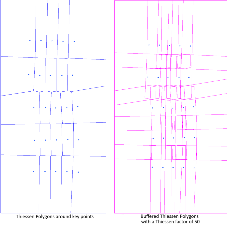
- Classic: Creates constraining polygons for the input images using PCI traditional algorithm that was developed for aerial images, that are approximately square and contain a lot of overlap. You can adjust the option by specifying a value for the Factor. In this case Factor represents the Theissen Factor. If you do not specify a value, the default value of 50 is applied.
- Strips: Create one constraint polygon for each input image using PCI algorithm that was developed for projects that have a clear pattern of strips, such as often seen with ADS data. Images must be of similar size and align in at least one direction from, for instance, aerial flight lines or satellite swaths. Cutline-constraining polygons is generated for each image based on where it and its neighbors have actual data. This method first tries to group the images in rows or columns, and chooses the strips with the most consistent distance between images. It then removes the overlap between images in each strip using, at most, two neighboring images. Finally overlap is remove between the different strips leaving a constraining polygon. The extents of the polygons can be manipulated by specifying a value for the overlap Factor. If you do not specify a value, the default value of 20 is applied.
- No: Does not apply constraint polygons.
You can adjust the effect of Auto Constrain by specifying an appropriate percentage value for Factor.
When a constraining layer is specified for Cutline Method Extra Options, do not use Auto Constrain; that is, select No.
Factor
The Factor is a percentage by which to adjust the effect of the Auto Constrain option.
This is a value between 1 and 100, with larger values causing more overlap between the generated constraint polygons; that is, the cutlines is less constrained.
Blend Width
The perpendicular distance from the cutlines over which image blending occurs.
Image blending is to average the gray value of each pixel in the blending strip along a cutline from both overlapping input images. If no value is specified for this parameter, no blending is performed.